Module 1 -- DC Circuits
Index
- Electrical Circuit Elements
- Voltage and Current Sources
- Kirchhoff's Laws
- Important Pre-requisites before understanding the kirchhoff's laws
- Kirchhoff's Current law (KCL)
- Kirchhoff's Voltage Law (KVL)
- Sign Convention for KVL
- A better example to understand both KCL and KVL
- Example 2 (KCL and KVL)
- Example 3 (KCL and KVL)
- Superposition, Thevenin and Norton's Theorems
- Superposition Theorem
- Example (Superposition Theorem)
- Thevenin's Theorem
- Norton's Theorem
- Relationship between Thevenin and Norton
- Example (Thevenin and Norton's Theorem)
- 🧭 DC Circuit Analysis — Reasoning Traces & Concept Map (Important summary to keep in mind for DC circuit's theorem and circuit analysis)
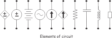
Electrical Circuit Elements
What is an Electric Circuit?
An electric circuit is an interconnection of circuit elements forming a closed path for electric current to flow. A circuit element is the most basic building block that cannot be subdivided further and is characterized completely by its voltage-current relationship.
The Three Passive Elements
There are three fundamental passive circuit elements: Resistor (R), Inductor (L), and Capacitor (C). These are called "passive" because they do not generate electrical energy—they either dissipate it or store it.
1. Resistor (R)
What it does: A resistor introduces electrical friction or resistance in the path of electric current.
Physical behavior: It opposes the flow of current and converts electrical energy into heat—similar to how friction in mechanics dissipates kinetic energy.
2. Inductor (L)
What it does: An inductor is a coil of wire that stores energy in a magnetic field when current flows through it.
Physical behavior: It resists changes in current—think of it like inertia in mechanics, where mass resists changes in velocity.
Voltage-Current Relationship:
where
Key characteristic: An inductor offers little opposition to steady DC current but strongly opposes AC current or any changing current. The energy stored in an inductor is:
3. Capacitor (C)
What it does: A capacitor stores electrical energy in an electric field between two conducting plates.
Physical behavior: It resists changes in voltage—like a spring storing potential energy when compressed.
Voltage-Current Relationship:
or equivalently:
where
Key characteristic: A capacitor blocks DC current once fully charged but allows AC current to pass. The energy stored is:
Voltage and Current Sources
These are the active elements that provide electrical energy to circuits, unlike passive elements (R, L, C) that either dissipate or store energy.
Types of Sources
Sources are classified into two main categories:
-
Independent Sources - their output doesn't depend on other circuit variables.
-
Dependent Sources - their output is controlled by another voltage or current in the circuit.
Independent Voltage Source
An independent voltage source maintains a constant voltage across it's terminals, regardless of the current drawn from it. Think of it as a "voltage enforcer".
Now, under voltage sources, there are two main types of voltage sources:
Ideal Voltage Source
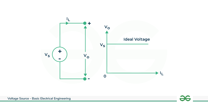
Characteristics:
- Supplies constant voltage regardless of load current
- Has zero internal resistance (
) - Terminal voltage always equals source voltage (no voltage drop)
- Can theoretically supply infinite current
- 100% efficient (no power loss)
Practical Voltage Source
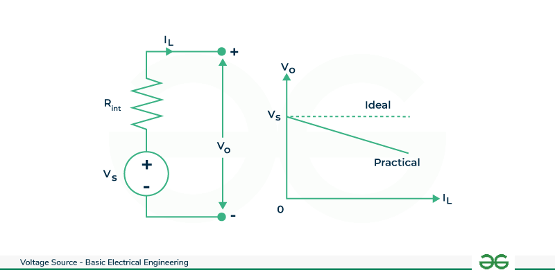
Characteristics:
- Has a small internal resistance (
) in series. - Terminal voltage drops as current increases:
- More realistic representation of real batteries and generators.
Direct Voltage Source
Devices or components in electrical circuits that produce a constant voltage output and maintain a constant potential difference across their terminals are referred to as direct voltage sources or direct current (DC) sources.
Output at a Constant Voltage
- Characteristic: The essential element of an immediate voltage source is its capacity to supply a consistent voltage level over the long run.
- Stability: This security is significant in applications where a steady electrical potential is required.
Unidirectional Current Flow
-
Flow of Charge: Electric charge (current) flows in a single direction in a direct voltage source. The negative terminal is replaced by the positive terminal by electrons.
-
Straightforward Circuitry: This effortlessness of the current stream makes DC sources appropriate for direct circuit plans.
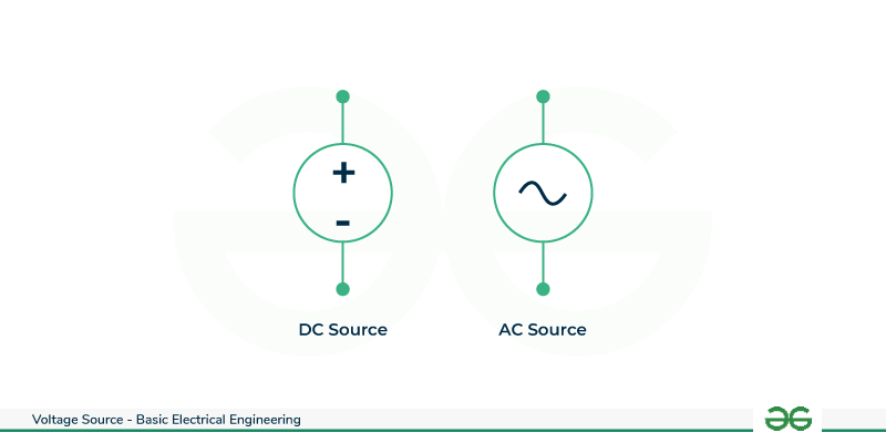
Alternating Voltage Sources
Alternating Voltage Sources, regularly referred to as Alternating Current (AC) sources, are gadgets or components in electrical circuits that produce a consistently changing voltage yield. AC sources, in contrast to Direct Current (DC) sources, produce a sinusoidal voltage that changes over time.
Sinusoidal Voltage Variation
-
Characteristic: The characterizing element of AC sources is the sinusoidal variety of voltage over the long run. This indicates that the voltage fluctuates between positive and negative values regularly.
-
Representation: The voltage waveform is frequently represented mathematically by a sine or cosine function.
Polarity Reversal
-
Polarity Change: The electric current in AC sources occasionally reverses direction. Electrons move to and froth, making a substituting stream.
-
Frequency: Hertz (Hz) is the unit of measurement for the rate at which the polarity shifts.
Common Types of Alternating Voltage Sources
-
Generators: Electromagnetic induction results in the production of alternating voltage by AC generators, such as those found in power plants.
-
Power Outlets: AC voltage is typically provided by household power outlets. AC at 60 Hz is the norm in many places.
Dependent Voltage Sources
A dependent voltage source is a type of voltage source whose output voltage is dependent on any other voltage or current in the circuit. Controlled voltage sources are two other names for dependent voltage sources.
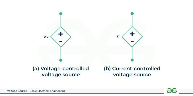
There are two types of controlled voltage sources:
- Voltage Controlled Voltage Source (VCVS) / Voltage Dependent Voltage Source (VDVS)
- Current Controlled Voltage Source (CCVS) / Current Dependent Voltage Source (CDVS)
Voltage-dependent Voltage Source
A voltage-dependent voltage source (VDVS) or voltage-controlled voltage source (VCVS) is a voltage source whose output voltage is dependent on the voltage in any other part of the electric circuit.
Current Controlled Voltage Source
n contrast, a voltage source is referred to as a current-dependent voltage source (CDVS) or a current-controlled voltage source (CCVS) when its output voltage is dependent on the current in any other part of the circuit.
Kirchhoff's Laws
Important Pre-requisites before understanding the kirchhoff's laws
https://www.electrical4u.com/nodes-branches-and-loops-of-a-circuit/
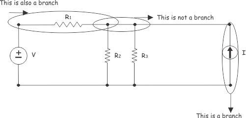
1. Branch
A branch is a single circuit element (like a resistor, voltage source, or capacitor) connecting two points, or any path containing a single element. Think of it as a "road segment" in our circuit.
Any circuit element connects between two nodes in the circuit. The path from one node to another through this element is called a branch of the circuit.
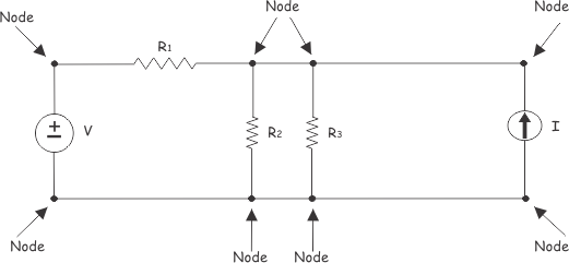
2. Node
A node is a junction point where two or more branches meet.
If three is no element between two or more connected adjacent nodes, these nodes can be recombined as a single node.
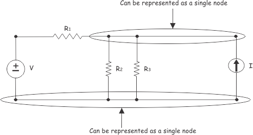
which can be re-drawn as:
3. Loop
A loop is any closed path in a circuit that starts and ends at the same node without crossing any node twice. Like tracing a circle around your circuit.
Series vs Parallel Circuits
These two configurations determine how current and voltage behave in your circuit.
Series Circuit
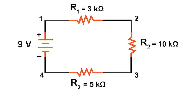
Definition: Components are connected end-to-end in a single path, forming one continuous loop.
Key Characteristics
-
Current behavior: The same current flows through all components. Think of water flowing through a single pipe—the flow rate is identical everywhere.
-
Voltage behaviour: =The source voltage is divided (shared) among the components=. Each component gets a portion of the total voltage.
-
Resistance: Total resistance is the sum of individual resistances.
Critical weakness: If one component fails, the entire circuit breaks—like old Christmas lights.
Parallel Circuit
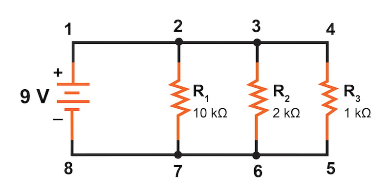
Definition: Components are connected across common points with multiple paths for current.
Key Characteristics
-
Voltage behaviour: The same voltage appears across all components. Each component connects directly to the source voltage.
-
Current behavior: The source current splits at junctions and divides among the branches. The sum of branch currents equals the total current.
-
Resistance: Total resistance decreases and is less than the smallest individual resistance. More paths mean easier current flow.
Quick Comparison Table
| Property | Series | Parallel |
|---|---|---|
| Current | Same through all components | Splits at junctions |
| Voltage | Divides among components | Same across all components |
| Resistance | ||
| Component failure | Breaks entire circuit | Others still work |
Why This Matters for Kirchhoff's Laws
Now here's the connection: Kirchhoff's Laws mathematically describe what we just discussed:
-
KCL (Kirchhoff's Current Law) explains how current behaves at nodes (especially relevant for parallel circuits)
-
KVL (Kirchhoff's Voltage Law) explains how voltage behaves around loops (especially relevant for series circuits)
Ohm's Law
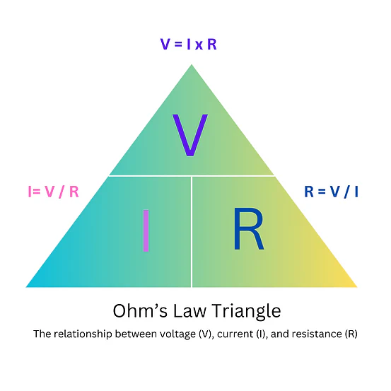
Ohm's Law describes the relationship between voltage, current, and resistance in an electrical circuit, stating that current is directly proportional to voltage and inversely proportional to resistance, as long as physical conditions like temperature remain constant.
The law is primarily expressed with the formula:
or in other forms as the image above shows.
Kirchhoff's Current law (KCL)
Also known as Kirchhoff's First Law or the Junction Rule.
The Law Statement
"The algebraic sum of all currents entering and exiting a node must equal zero".
Or equivalently: "The total current entering a junction equals the total current leaving that junction".
Mathematical Expression
or written another way:
Why is the sum zero?
We’re saying:
“If we give every branch current a sign based on our direction convention, their algebraic sum must equal zero.”
In other words:
-
Outgoing currents get a
-
Incoming currents get a
-
The total signed sum =
where you treat currents entering as positive and currents leaving as negative (or vice versa—just be consistent).
Physical Basis
KCL is based on the Law of Conservation of Charge. A node is just a connection point—it cannot create, destroy, or accumulate charge. Therefore, whatever charge flows in must flow out.
Think of it like water at a pipe junction: the amount of water flowing in equals the amount flowing out (assuming no leaks or storage).
Simple Example
Consider a node with 5 branches: currents
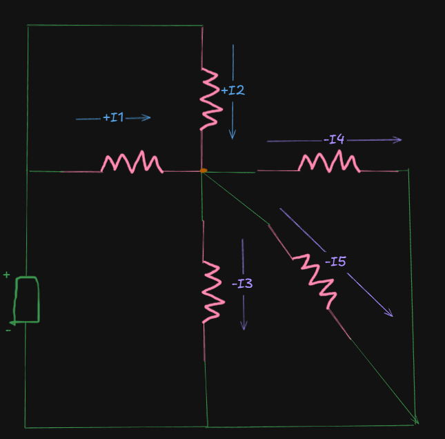
Well here is this odd looking circuit here, that has two incoming branches and 3 outgoing branches, all from a single node.
Applying KCL (entering currents = positive, leaving currents = negative)
Rearranging, we get:
This confirms: total current in = total current out.
When to use KCL
Apply KCL at nodes (junctions) where you need to find unknown currents, especially useful for analyzing parallel circuits.
Kirchhoff's Voltage Law (KVL)
Also known as Kirchhoff's Second Law or the Loop Rule.
The Law Statement
"The algebraic sum of all voltage differences around any closed loop is zero".
Or equivalently: "The sum of voltage rises equals the sum of voltage drops around a closed loop".
Mathematical Expression
around any closed loop.
Physical Basis
KVL is based on the Law of Conservation of Energy. When you traverse a complete loop and return to your starting point, you must be at the same electrical potential—you can't gain or lose net energy going in a circle.
Sign Convention for KVL
This is crucial! When traversing a loop:
Voltage Sources:
-
Moving from - to + terminal: counts as positive (voltage rise)
-
Moving from + to - terminal: counts as negative(voltage drop)
Resistors/passive elements:
-
Moving against current direction (- to +): positive (voltage rise)
-
Moving with current direction (+ to -): negative (voltage drop)
Simple Example
Consider a loop with a voltage source
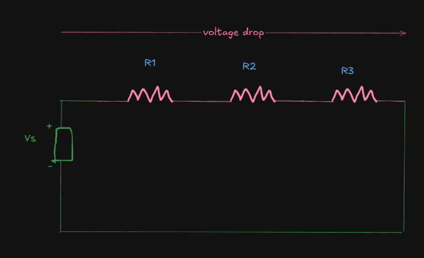
Applying KVL clockwise:
So, the net voltage remains zero.
Now, if we apply ohm's law here (
We get:
This shows how source voltage divides across resistors in series.
When to use KVL
Apply KVL around loops when you need to find unknown voltages or relate voltages in a circuit, especially useful for analyzing series circuits.
A better example to understand both KCL and KVL
(Also falls under the topic of Analysis of Simple DC circuits)
https://www.youtube.com/watch?v=2Zu3ppq3n8I (KCL, KVL and Ohm's law)
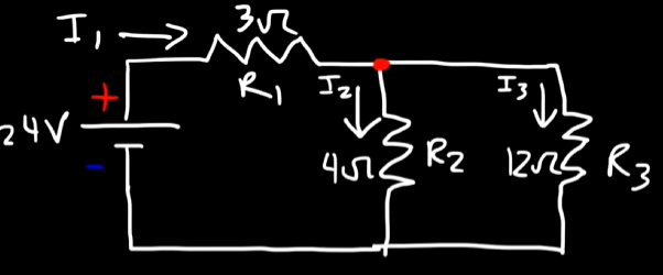
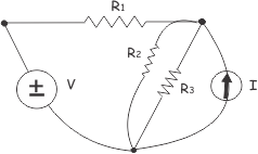
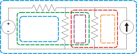
Say we have this circuit here.
And we are tasked to find out the currents
So, first, we have to analyze the voltage flow using the loop rule of Kirchhoff.
We know that:
-
Moving from - to + terminal: counts as positive (voltage rise)
-
Moving from + to - terminal: counts as negative(voltage drop)
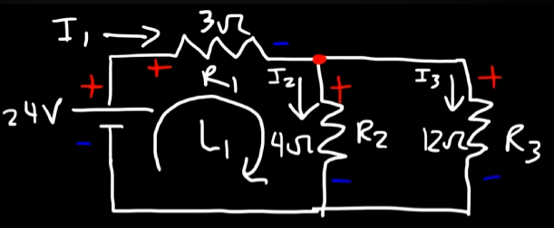
So, by analyzing the circuit as a whole, we see that current
From that current split, using KCL, we can get this equation:
So in this loop
So, for both the resistors involved in the loop
From KVL, the sum of all voltages in a circuit loop must equal to zero.
So,
That's equation 2.
Now, from the second loop:
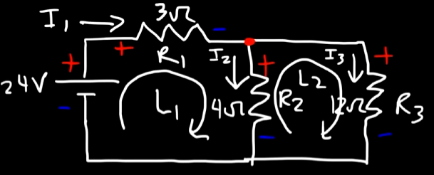
The current will start flowing from
So, for
So, we have:
For
So, we have:
Using KVL, we get:
So, in total, we got 3 equations:
Now it's just plain linear algebra from here on out.
So, by solving these equations we get:
Example 2
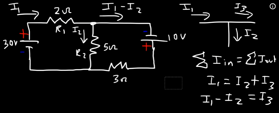
So, we have another circuit, however this time it has two voltage sources.
We will, similarly make loops and analyze the circuits to find out the current flowing through each of the resistors
The part that you see in the picture that the leaving current from the node that's supposed to be
That comes from the equation:
Which is then rearranged to be:
Anyways, so in loop 1.
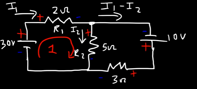
We have the voltage source:
For resistor
For resistor
By KVL, we have our equation:
or:
Next, for loop 2:
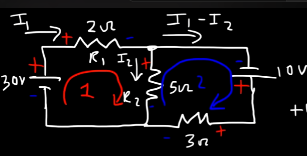
We have the secondary voltage source:
The voltage current flows from
For,
Or:
Next, for
Thus,:
So, by KVL, we have our second equation:
or:
or:
Now, we have all our equations:
Now, getting the current values is a matter of simple linear algebra.
By solving the equations, we get the three current values as:
Now, further on, if we were to find out the exact voltage drops per resistor, we can easily do so now, by applying ohm's law per resistor with their current values.
So, for
For
For
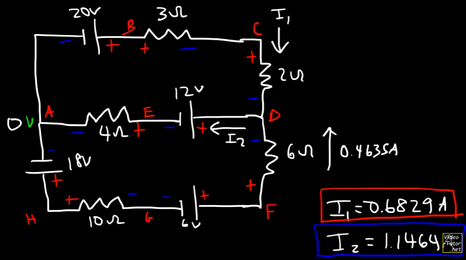
Example 3
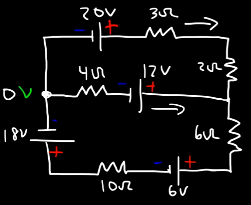
Now, we have to deal with this scary looking circuit.
Starting with loop 1.
We have a clockwise loop.
For the
So, that's
Now, the
Thus,
Now, when the
So, by KCL, we get an equation:
Or,
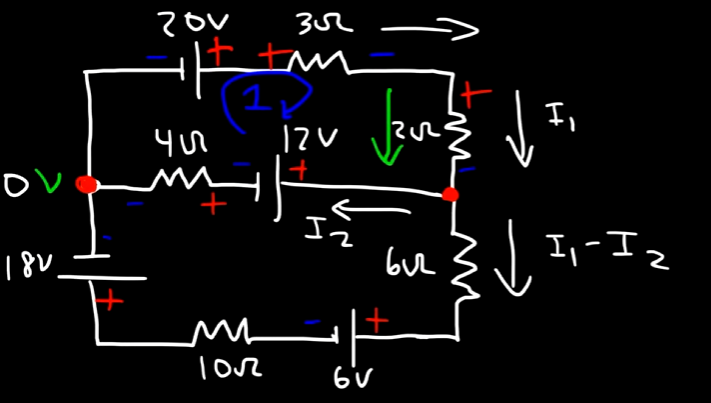
Focusing on loop 1 only, for the 12V source, the current goes from the positive to negative terminals, continuing the voltage drop.
So we have this down as
Next for the
So, that will be
So, for the loop 1, by KVL, we have the equation as:
or:
Next up we have loop 2:
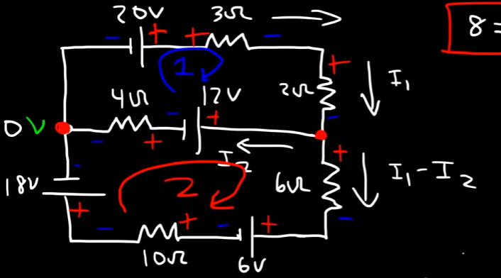
Starting from the 12V source:
For the
Then comes the 6V source having a voltage drop as well.
Then comes the
Then comes the 18V source with a voltage drop as well.
Lastly at the end of the loop comes the
So, the equation for this loop will be:
or:
or:
So, we now have the three equations:
Getting the current values from here on out is a simple matter of linear algebra.
Thus, by solving the equations, we can get the current values as:
Now, we have encountered a fundamental problem.
Thus our initial assumption that
The current split at the junction is fundamentally the same, but the true direction of flow is the reverse of what we assumed.
So,
Now that's going to give us a positive current value of
Now, you must be thinking, so how do I know how to make the correct assumption while predicting the flow of current?
The short answer: You don't. You make an assumption, then follow through with the math, and the math provides the verification you need to check which direction the current was flowing per branch (source or resistor) of the circuit.
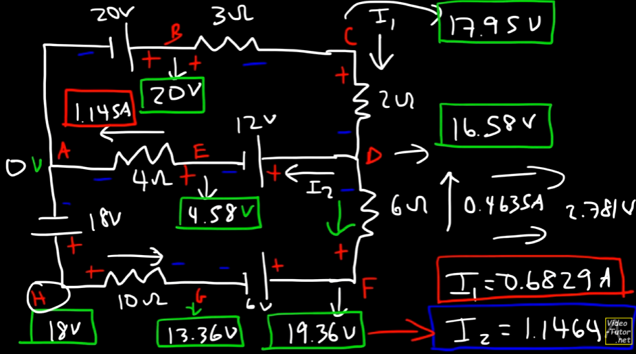
The corrected signs accordingly are:
You can see that the terminals for the lower half of the circuit, for loop 2, have been reversed to match the flow accordingly, specifically the
Now that we have all the current values, calculating the voltage at each junction would be easier if we just followed ohm's law per resistor and then proceeded with subtraction and addition as per the voltage drops/lifts as it is in the circuit.
There is one more example in the video, but since these 3 examples would more than suffice to cement the understanding of KCL, KVL and analysis of DC circuits, the last one is left open-ended for the reader's understanding.
Superposition, Thevenin and Norton's Theorems
Superposition Theorem
https://www.youtube.com/watch?v=EX52BuZxpQM
The Superposition Theorem states that in a linear circuit with multiple independent sources (voltage or current), the total current or voltage at any point is the algebraic sum of the currents or voltages produced by each source acting alone.
Physical Principle
This theorem exploits the linearity of circuit elements—meaning the response is directly proportional to the input. It breaks a complex multi-source problem into simpler single-source problems.
How to Apply Superposition Theorem
Follow these systematic steps:
Step 1: Choose one independent source to keep "active"
Step 2: "Turn off" all other independent sources:
- Replace voltage sources with a short circuit (0V)
- Replace current sources with an open circuit (0A)
- Keep all resistors in place
Step 3: Analyze the simplified circuit using Ohm's Law, KVL, KCL, or other methods to find the contribution of that one source
Step 4: Repeat Steps 1-3 for each independent source in the circuit
Step 5: Add algebraically all the individual contributions (considering signs/directions) to get the total current or voltage
Example
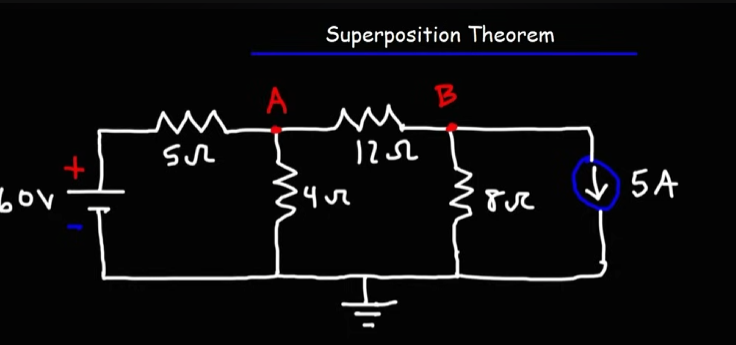
Let's take this circuit for an example.
To find out all the current values per resistors, voltage on the nodes we have to find out the values per source individually, then add them up in the end.
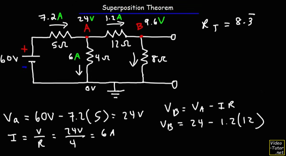
First Half
So, for the 60V source. Notice that the
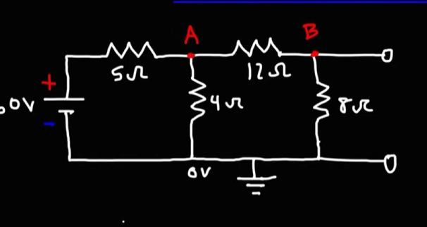
Using KCL, let's say the current going into the
By KCL:
For loop 1: assuming the flow of current to be in a clockwise loop,
for the
for the
So, by KVL, we get the equation as:
For loop 2:
For the
For the
For the
The equation becomes:
or:
From equation 1:
Applying this in equation 2:
Substituting
Now,
The voltage drop at the
So, the voltage at node A would be:
Voltage drop at the
Thus the voltage at node
And that matches what we did, although the person in the video took a much simpler approach than I did.
Second Half
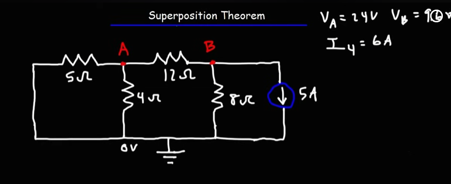
Time to solve for the
This time, we will perform nodal analysis that uses KCL, instead of mesh analysis, that uses KVL.
Before we proceed:
What exactly are the rules for nodal analysis?
When we do nodal analysis, we:
- forget about “which way” the wire bends,
- forget the shape of the circuit,
- and focus purely on connections between nodes and voltage differences.
This means that from the circuit diagram, for a node, even if you see that a resistor precedes a node, the current from the resistor to that node is not considered as "entering", but as leaving the node.
Why? Since from the node's perspective, that's...what the current does practically. It leaves the node.
Unless you explicitly see a current source deliberately entering a source, with a given arrow as well, which will be considered as entering the node, in all other cases, from a nodal analysis point of view, it's just the current leaving the node.
And of-course, the sign convention (default):
- Currents leaving the node = positive.
- Currents entering the node = negative.
Starting off with the first node branch off:
For the
Same logic:
The equation would be:
or:
That would be valid mathematically if we were still thinking from a KVL perspective.
However from Why is the sum zero? we know that:
So,
Now, you might be wondering? Why do the
Well, I'd say you got got, since you fell for a very neat optical illusion, that even I did too at first, compounded with a missing definition.
First off,
- The voltage for an electrical component is determined by the electric potential difference between it's two terminals.
If you notice the ends of the
They actually are like this:
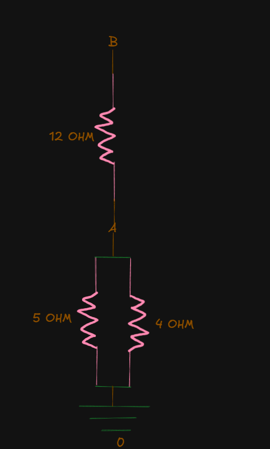
So, the
Now, for the
And for the
Now that all confusions are cleared up, let's proceed to the second node.
For node B:
You might be wondering: Why
To answer that:
If you used the same sign form
in both node equations, you’d be implying the current leaves both nodes simultaneously in the same direction — which violates KCL (current can’t flow out of both ends of a resistor at once).
You can think of it like two people describing the same tug-of-war rope:
-
Person A says, “I’m pulling on the rope to the right with 10 N.”
-
Person B says, “I’m pulling on the rope to the left with 10 N.”
They’re describing the same force, just in opposite reference directions — exactly like:
The extra 5 amps comes from the current of
So, we have the two equations:
and:
From the first equation:
From the second equation:
Applying the value of
Now:
Thus,
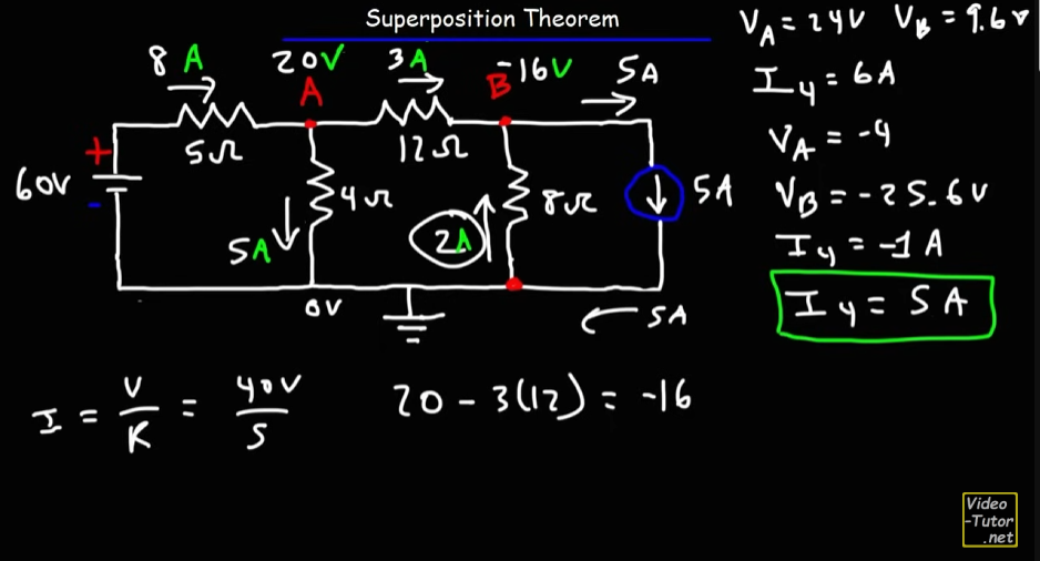
Total currents and voltages
Now, it's time to add up the current and voltage values obtained from both sources:
From first half (60 V source), we had:
From the second half (5A source), we have:
Notice a discrepancy?
You might be thinking,
For the 60V source the current values for
That's because of how the circuit structure(topology) changed when we added and removed the sources in each half of the calculation.
The resistors were in series in both cases, but the circuit topology changed during the 5A source, node B became a junction instead since the current from node A arrived at node B, and further branched off, one part to the
So, finally
(using Ohm's law here.) (same as
same as
Can also be obtained by:
Also obtainable by:
And that's exactly as the values in the video:
And that's it for the superposition theorem! This numerical hopefully cleared up a lot of concepts and potential confusions underlying the analysis of DC circuits using KCL and KVL too.
https://www.youtube.com/watch?v=EX52BuZxpQM (same video)
There's another example in the video, which you can follow up with for even more practice!
Advantages and Limitations of Superposition Theorem
Advantages
-
Simplifies analysis of complex multi-source circuits
-
Each single-source circuit is easier to solve
-
Useful for understanding individual source contributions
Limitations
-
Can be time-consuming if many sources exist
-
Not applicable to nonlinear circuits (with diodes, transistors, etc.)
-
Cannot directly calculate power (must find voltage/current first, then calculate power)
Thevenin's Theorem
Thevenin's Theorem states that any linear two-terminal network containing voltage sources, current sources, and resistors can be replaced by an equivalent circuitconsisting of a single voltage source
The Thevenin equivalent circuit
Original complex circuit
where:
-
is the Thevenin voltage, Open-circuit voltage across the terminals. -
is the Thevenin resistance, equivalent resistance seen from the terminals with all sources deactivated.
How to find the Thevenin Equivalent Circuit?
Step 1: Identify the two terminals (a-b) across which you want the equivalent circuit.
Step 2: Remove the load (usually a load resistor) (if any) connected between terminals a-b.
Step 3: Find
-
This is the open-circuit voltage (
) across terminals a-b -
First use superposition theorem to find out the voltages and currents from individual sources (in most cases that will be the case), then add them up, focus specifically on the voltages of the two terminals. Use any circuit analysis method (KVL, KCL, nodal, mesh)
-
Thus,
, the difference of the voltages of the two terminals.
Step 4: Find
If only independent sources:
-
Deactivate all independent sources:
-
Replace voltage sources with short circuits.
-
Replace current sources with open circuits.
-
-
Calculate the equivalent resistance looking into terminals a-b
If dependent sources are present:
-
Find short-circuit current (
) across terminals a-b -
Then:
Why Use Thevenin's Theorem?
Advantage: When the load changes frequently, you don't need to re-analyze the entire circuit—just use the Thevenin equivalent with the new load. This is especially useful in power system analysis and electronic circuits.
Norton's Theorem
The Statement
Norton's Theorem states that any linear two-terminal network can be replaced by an equivalent circuit consisting of a single current source
The Norton Equivalent Circuit
Original complex circuit → Simplified to:
where:
is the Norton current - Short-circuit current through the terminals is the Norton resistance - Same as Thevenin resistance ( ).
How to find the Norton Equivalent
The steps are similar to that of finding the Thevenin equivalent
Step 1: Identify the two terminals (a-b) across which you want the equivalent circuit.
Step 2: Remove the load (usually a load resistor) (if any) connected between terminals a-b.
Step 3: Find
- This is the short-circuit current (
) that flows when terminals a-b are shorted.
Step 4: Find
- Same procedure as finding
Relationship between Thevenin and Norton
These two theorems are equivalent and interchangeable through source transformation:
Example
https://www.youtube.com/watch?v=-kkvqr1wSwA (This video explains both Thevenin's and Norton's Theorem)
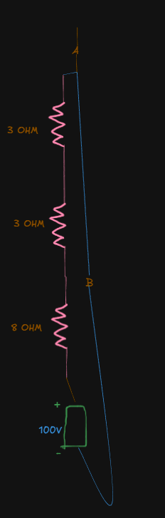
This is the given circuit. Notice that we have two sources, one a 100V battery, a 7A source. And also a load resistor.
We have two terminals A and B of the load resistor.
Step 1: Finding the Thevenin resistance
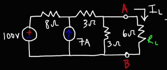
- Remove the load resistor
- Replace voltage source with closed circuit
- Replace current source with open circuit
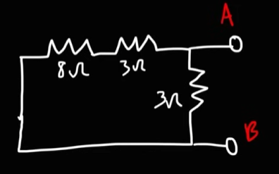
Now we simply analyze the circuit to find the total resistance, which will be our Thevenin Resistance
Now, the
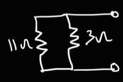
Now, the total resistance or the Thevenin resistance here would be:
Next, use superposition theorem to find the individual voltages and currents from both sources and add them.
For the 100V source:
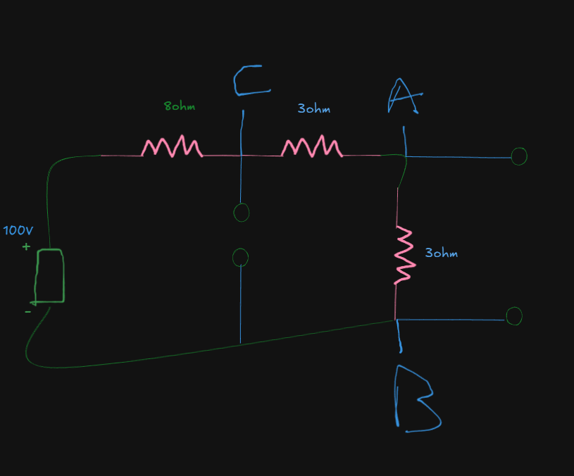
Now, it's not really necessary to go the KVL route here and make things overcomplicated when all we can really do is this:
The 3 resistors are in series.
Thus they will share the same current values.
So, we can bundle them into a single resistor of
The current would be:
For the
The drop would be:
For the upper
The voltage drop for node A would be:
Next, for the second
For the voltage drop at node B:
which is basically the negative terminal of the battery, so it's negligible here. This value already confirms our reference point that node B is the ground here.
Now, for the 7A source:
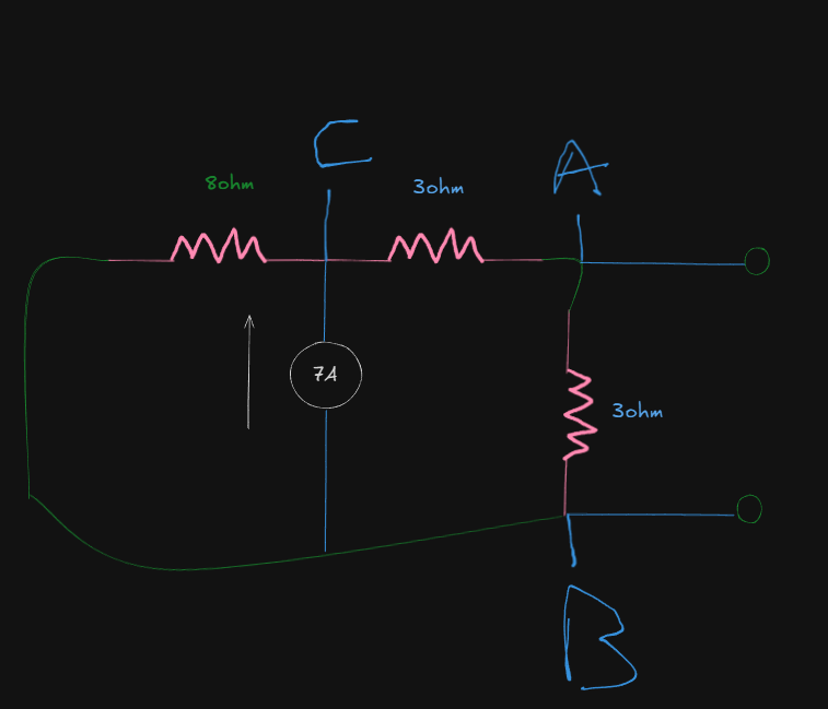
Using nodal analysis here:
If we name the current going into node C from resistor
For node C:
Here
So, the equation simplifies to:
For node A:
or:
Applying this value in the previous equation:
So:
The current values are:
Just to recap:
From the 100 V source we had:
- The current was
for all 3 resistors.
From the 7A source:
Superimposing, we get:
So, the Thevenin Voltage
since (
Finally the Norton Current:
The Thevenin Resistance we found out way earlier was:
which is just the same in the video:
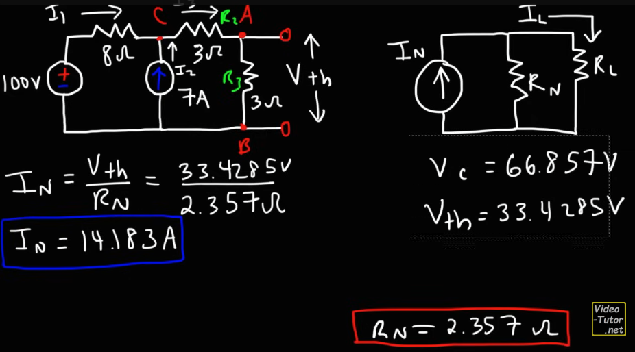
(Ignore minor rounding differences due to different calculators used)
🧭 DC Circuit Analysis — Reasoning Traces & Concept Map
Culmination of all the realizations I made in my own language for all DC circuits.
Core idea: Circuits are networks of nodes and connections, not drawings of wires.
Geometry doesn’t matter — connectivity does.
⚡ 1. Foundational Mindset
- Every resistor is a bridge between two nodes.
- Circuit analysis = applying conservation of charge (KCL) and energy (KVL).
- Pick one reference node (0 V).
You don’t find ground — you define it. - Results depend only on voltage differences, never on absolute values.
🔌 2. KCL (Nodal Analysis)
“At every node, the sum of currents leaving = 0.”
- Assign node voltages:
, , , etc. - Choose one node as 0 V (reference).
- For each node:
- For every resistor connected, write
I = (V_node - V_other) / R.
(Defined as leaving the node.) - For current sources:
+Iif it leaves the node.−Iif it enters the node.
- For every resistor connected, write
- Sum all currents leaving = 0.
- Solve the resulting equations.
- A negative result ⇒ actual direction opposite to assumption.
🧠 Mental model:
Each node is like a bubble. The “pressure” (voltage) in it adjusts until no net flow of charge occurs.
🔁 3. KVL (Mesh Analysis)
“Around any closed loop, total voltage rises and drops = 0.”
- Identify independent meshes (loops).
- Assign each a loop current (CW or CCW).
- For each loop:
- Write
ΣV = 0, summing voltage drops and rises. - For resistors:
V = I × R. - For shared resistors: use the difference
(I1 − I2).
- Write
- Solve the system for loop currents.
- A negative value = actual direction opposite to your guess.
🧠 Mental model:
Each loop is an energy story — sources give, resistors take, and the “budget” balances to zero.
🧮 4. Superposition Theorem
“The total response = sum of each source acting alone.”
- Identify all independent sources.
- For each subcase:
- Keep one source active, turn others off:
- Voltage source → short circuit.
- Current source → open circuit.
- Solve for desired currents/voltages.
- Keep one source active, turn others off:
- Add results algebraically (consider signs).
- Superposition applies to linear circuits only.
🧠 Mental model:
Each source plays its own “melody”; the circuit’s behavior is the harmony of all their songs.
🔋 5. Thevenin & Norton Equivalents
“Simplify any linear network into a single source and a single resistor as seen from two terminals.”
Finding RTh (or RN)
- Deactivate all independent sources:
- Voltage source → short.
- Current source → open.
- Look into the circuit from the terminals (A–B).
- Combine resistors using series/parallel to find the equivalent resistance.
Finding VTh
- Reactivate all sources.
- Remove the load (open circuit across A–B).
- Use KCL/KVL or superposition to find the open-circuit voltage:
V_Th = V_A − V_B.
Finding IN
🧠 Mental model:
From the load’s perspective, the entire circuit behaves like one simple source with internal resistance.
🔄 6. Sign & Direction Logic
- You’re free to assume current directions and voltage polarities.
The math will correct you if wrong. - A negative current just means flow is opposite to your assumption.
- Physical intuition (current flows high → low potential) is for checking, not defining.
- Stick to one consistent sign convention per node.
🪄 7. Topology Tips
- Series: Same current through all elements (single path).
- Parallel: Same voltage across all elements (share both endpoints).
- If two resistors of equal value connect a node to two other points,
that node’s voltage is halfway between them. - Deactivating sources can change topology — always redraw.
- Symmetry in resistors → look for proportional voltage relations.
🧠 8. Grounding Principle
- “Ground” = the node you define as 0 V.
- Choose the node:
- with the most connections, or
- that returns to the main source’s negative terminal.
- Any node can be reference — only voltage differences matter.
🎯 9. Meta Reasoning Checklist
- ✅ Redraw complex circuits to clarify nodes.
- ✅ Label every node and current direction before writing equations.
- ✅ Check if sources change circuit connectivity when deactivated.
- ✅ Always write equations symbolically first — substitute numbers later.
- ✅ When stuck, use energy/charge conservation intuition instead of blindly solving.
🧩 10. Quick Cheat Lines
- KCL: “All roads lead to 0 net current per node.”
- KVL: “Every loop pays its energy bill in full.”
- Superposition: “Each source plays its solo; the total is the symphony.”
- Thevenin/Norton: “Circuit shrink rays for linear worlds.”
- Ground: “You don’t find it — you define it.”
- Signs: “Direction is just language; the math tells the truth.”
✅ 11. Summary of Key Equivalences
| Concept | Expression | Physical meaning |
|---|---|---|
| KCL | ΣI (leaving node) = 0 | Charge conservation |
| KVL | ΣV (around loop) = 0 | Energy conservation |
| Ohm’s Law | V = I·R | Linear resistance relation |
| Superposition | V_total = ΣV_i | Linearity principle |
| Thevenin ↔ Norton | V_th = I_N·R_th | Dual representations |
Final mindset:
Circuit diagrams show the physical world; nodal equations describe the logical world.
Once you can switch between the two, you’ve mastered DC circuit reasoning.