Module 2 -- AC Circuits
Index
- Representation of Sinusoidal Waveforms
- Phase Difference
- Peak and RMS values
- Phasor Representation
- Complex Number forms
- AC Circuit analysis using Phasors
- Impedances
- Three types of power in AC circuits
- 1. Real Power (Active Power)
- 2 Reactive Power
- 3. Apparent Power
- Analysis of Single Phase AC Circuits
- Resonance in single phase AC circuits
- Three Phase AC Circuits
- The Connection Methods
- Power in Three-Phase Systems
Representation of Sinusoidal Waveforms
Sinusoids
https://www.youtube.com/watch?v=YhpOZcjrvQM
What exactly are these sinusoids?
Sinusoids are signals that look like sine or cosine functions.
A sinusoid is represented by an equation like:
And a sinusoidal (AC) voltage or current varies with time according to:
where:
-
is the instantaneous voltage at time seconds. -
is the amplitude or maximum value of the voltage. (The maximum arc, a crest or trough can stretch to in the signal).
-
is the angular frequency in radians per second. The angular frequency of a wave is a measure of how quickly a wave's phase changes over time, representing the angular displacement per unit of time. The phase of a wave is basically any point in the wave within a single cycle.
The phase difference would mean the difference between any two chosen points on the wave in a single cycle.
-
is the time. -
is the frequency in Hertz (Hz) -
is the time period which is seconds. -
is the phase angle (in radians or degrees)
Periodicity
-
Sinusoids are periodic signals, meaning their waveform repeats itself.
-
The fundamental time period (T) is the minimum time after which the signal repeats.
Assuming you already did DC circuits before getting here, think of AC as voltage/current that changes magnitude and direction periodically.
Essential Relationships
Time Period & Frequency:
For example: If
-
-
.
Phase Difference
When comparing two sinusoids of the same frequency:
The second waveform leads by
Quick Practice
A voltage
Find:
- The Peak value
- Frequency
- Time Period.
Using the formula:
The
-
The peak value (we will learn more about it in the next section),
-
The Frequency is given by:
-
The Time period is given by:
.
Peak and RMS values
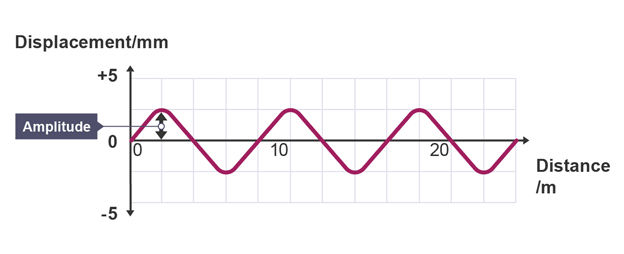
Peak Value
The peak value (
For the sinusoid
Visual Understanding
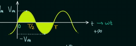
If you imagine a sine wave oscillating up and down:
- It starts at zero
- Rises to it's peak value at
(positive maximum or positive peak) - Returns to zero at
. - Drops to it's negative peak at
(which has the same magnitude as the positive peak) - Returns to zero at
, cycle complete.
Peak-to-Peak Value: The total swing from negative to positive peak is
RMS Value
The RMS value of alternating current is defined as: the steady DC current which, when passed through a given resistance for a given time, produces the same amount of heat as produced by the alternating current through the same resistance for the same time.
Think of it this way
Imagine two scenarios with the same resistor:
-
AC Scenario: An AC current
flows through a resistor for 1 minute. -
DC Scenario: A steady DC current of
flows through the same resistor for 1 minute.
Both produces exactly the same amount of heat! That 7.07 A DC value is the RMS value of the AC current.
Why This Matters
-
The RMS value is also called the "effective value" because it represents the effective heating capability of AC
-
All electrical instruments (ammeters, voltmeters) measure RMS values
-
When you see "230V AC" on your appliances, that's the RMS voltage, not peak.
-
Power calculations in AC circuits use RMS values:
.
Quick Example
If an AC produces the same heat as a steady DC of 4A, then the RMS value of that AC is 4A (not the resistance). The peak value would then be:
RMS Formulae
For a sinusoidal waveform:
The inverse relationship will be:
Some examples to understand Peak and RMS values
Problem 1: A sinusoidal voltage has a peak value of 340V. Find the RMS value.
Solution:
Problem 2: The domestic AC supply is 230V, 50Hz. Find: (a) Peak voltage, (b) Equation of voltage.
Solution:
Here, the 230 V is not voltage, but the RMS voltage.
So, we need to find the amplitude of the sinusoidal equation of this supply, which will be the peak voltage.
(a) Peak voltage:
(b) Now we need to find the angular frequency of the wave, which is given by:
Now the equation of voltage is given by:
since we don't have
or:
Problem 3: An AC current is given by
From the given sinusoidal equation:
We have:
The peak current value (amplitude) as:
The angular frequency,
So, the RMS current value would be:
Phasor Representation
https://www.youtube.com/watch?v=qyKEw9X-yHQ
A phasor is a complex number that represents two key pieces of information about a sinusoid: its amplitude and its phase angle.
Conversion: Time Domain to Phasor Domain
For a sinusoid that's in the time domain:
The equivalent phasor form(using RMS) would be:
where
Say, if we have a sinusoidal wave equation:
where the amplitude is 3 and the phase angle is 30 degrees
It can be represented with a phasor as:
For it's phasor representation using RMS:
Time Independence: A crucial aspect of phasors is that they are time-independent. The time involved components are suppressed when a sinusoid is converted to a phasor and that simplifies analysis.
Complex Number forms
Phasors are expressed as complex numbers, most commonly in:
1. Polar Form
The standard form that we just explored:
or with RMS:
2. Rectangular (Complex) Form
where:
(Real part) (imaginary part)
Example:
Conversion between forms
Polar to Rectangular:
Rectangular to Polar:
Quick Example
Problem: Convert
For phasor form:
Thus the phasor is:
where:
For the rectangular form:
AC Circuit analysis using Phasors
https://www.youtube.com/watch?v=YrtZgA05MBI
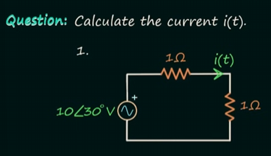
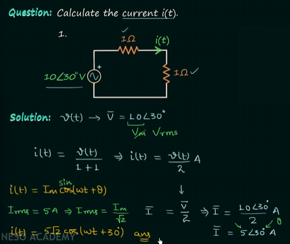
Example 1
Impedances
Quick pause before we proceed with the solving.
Impedance (
Now that we are done, let's get back to the problem.
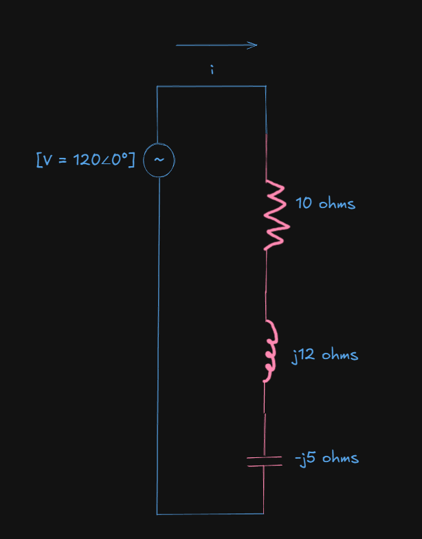
We have been given:
-
A source in phasor form:
. -
Two resistors in series, both
each. -
Current arrow
flows clockwise (through the top resistor then down the right ).
So, firstly what we will do is combine the impedances(resistances) which are in series.
Total impedance
Using ohm's law we can find out the total current in the circuit:
Optionally we can convert to the rectangular form as well (for better practice):
We can further verify our own answer.
For each resistor, there will be a voltage drop.
Voltage drop for each
A KVL check would result in:
Final answer: Convert back to sinusoid (time domain)
Here be careful about your phasor convention:
-
If the voltage (or current) is given in the phasors form, which are given in polar forms, the numeric part are the RMS values, by default convention.
-
If the voltage (or current) is given in sinusoidal form, you would get the phasor in peak voltage form, not RMS, thus converting it back to the resulting sinusoidal would just directly fit in the sinusoid equations.
In our case, we have RMS values.
So,
will be converted to it's peak value equivalent in the sinusoid for the instantaneous current.
So the instantaneous current is:
or:
(Textbooks commonly use RMS phasors; confirm from your course which convention they use. If nothing is said, RMS is safest.)
And that's exactly what it is in the video:
Example 2
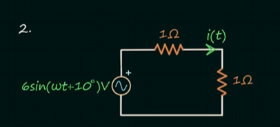
Given here is a sinusoidal voltage.
The resistances are the same and the current is the same as the previous problem.
So the total impedance (
Converting the voltage to a phasor form:
The current would be:
Converting back to sinusoidal form:
https://www.youtube.com/watch?v=47hGRVA3K98
This video contains even more examples related to phasors
Key Advantage of using phasors
Addition/subtraction of AC quantities: Instead of adding complex sine functions, just add phasors as vectors!
Example:
Using phasors:
Power in AC Circuits
In DC circuits, power was simple:
Now hold on a minute.
What does it mean to be "in phase" and "not in phase"?
For that, let's just wind back to our definition of phase in a wave:
The phase of a wave is basically any point in the wave within a single cycle.
The phase difference would mean the difference between any two chosen points on the wave in a single cycle.
For a general sinusoidal signal:
-
: tells you where you are in time within a cycle (A cycle starts when and ends when ). -
: tells how much the wave is shifted horizontally (left or right) compared to a reference.
So, if two waves have different
What "in phase" means:
If two sinusoids of the same frequency rise, peak, cross zero, and fall at the same time, they are in phase.
Mathematically:
Here
Their peak lines up perfectly.
An example would be:
Imagine two sinusoids on top of each other:
v(t):    ~~~~~~~~^^^^~~~~~~~^^^^~~~~
i(t):    ~~~~~~~~^^^^~~~~~~~^^^^~~~~
- Both cross zero and reach peaks simultaneously.
- This happens in pure resistive circuits — no energy stored, all power converted to heat.
That's what being "in phase" means.
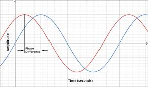
What being "out of phase" or "not in phase means"
Now imagine:
If
This is called a phase difference (or phase shift).
-
lags behind if (current occurs later). This happens in inductive circuits. -
leads if (current occurs earlier). This happens in capacitive circuits.
Example:
v(t):    ~~~~~~~~^^^^~~~~~~~^^^^~~~~
i(t):      ~~~~~~~~^^^^~~~~~~~^^^^~~
- Current wave is shifted to the right(lags).
- Same frequency, different timing.
The phase angle
Think of
- One full cycle is
or radians - So a
phase difference means the second wave reaches its peak of a cycle later.
In AC analysis:
- For a resistor:
- For an inductor:
(current lags) - For a capacitor:
(current leads) - For any R-L-C combo:
lies between and
Imagine voltage as “effort” and current as “resulting motion.”
If both are synchronized (in phase), all your effort goes into useful motion (real work).
If not, part of your effort goes into pushing and pulling energy back and forth — that’s reactive power.
For people who have learnt machine learning, specifically cosine similarity and how vector embeddings work here's a neat connection build up the full intuition:
Like in vectors, specifically while performing cosine similarity we can tell how similar a vector is to another based on their angle, with the most similar for the angle being 1 .
In cases of sinusoids and their phase angles, the sinusoids are literally similar to each other since they overlap on each other due to their phase angle, i.e. angular time delay between them being zero. They start together and end together.
That's what it means to be in phase.
Now, dissimilar vectors have an angle of zero.
Similarly when two sinusoids' phase angle is not equals to zero, then they are not that similar to each other, in wave terms, one started earlier and the other lagged behind it by a certain time delay, which is the phase angle.
That's what it means to be out of phase.
Three types of power in AC circuits
1. Real Power (Active Power)
Definition: The actual power consumed by the circuit that does useful work (produces heat, light, motion).
Symbol:
Unit: Watts
Formula:
where
Key Point: Only the component of current in phase with voltage contributes to real power. Real power is consumed by resistive elements (R)
2 Reactive Power
Definition: Power that oscillates back and forth between the source and reactive elements (inductors and capacitors) without doing any useful work.
Symbol:
Unit: VAR (Volt-Ampere Reactive)
Formula:
Key Point: The component of current 90° out of phase with voltage contributes to reactive power.
3. Apparent Power
Definition: The total power supplied by the source, combining both real and reactive power.
Symbol:
Unit:
Formula:
Relationship with P and Q:
or in complex form:
Apparent power is used to rate electrical equipment like transformers and generators.
Power Triangle
The relationship between these three powers forms a right-angled triangle:
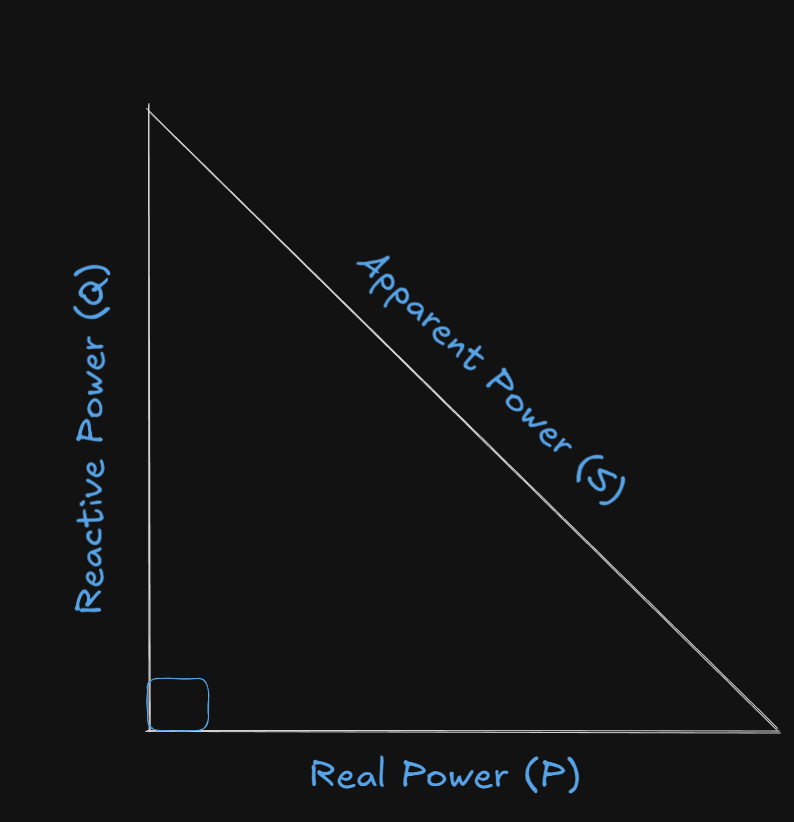
- Horizontal side (adjacent): Real Power (P)
- Vertical side (opposite): Reactive Power (Q)
- Hypotenuse: Apparent Power (S)
From the triangle:
( ) ( ) (Pythagoras's Theorem)
Power Factor
Definition: The ratio of real power to apparent power
Range: 0 to 1 (or 0% to 100%)
Significance:
-
Power factor = 1 (unity): Purely resistive circuit, all power is real power
-
Power factor = 0: Purely reactive circuit, no real power consumed
-
Leading power factor: Capacitive load (current leads voltage)
-
Lagging power factor: Inductive load (current lags voltage)
Essential Formulae Summary
| Power Type | Symbol | Unit | Formula |
|---|---|---|---|
| Real Power | W (Watts) | ||
| Reactive Power | VAR (Volt-Ampere Reactive) | ||
| Apparent Power | VA (Volt-Ampere) | ||
| Power Factor | - |
And
Why
When we learned power:
and
This
| Case | Effect | Behaviour | |
|---|---|---|---|
| In phase | All power converted to heat/work | Purely resistive | |
| Voltage leads by |
No real power transfer (Q positive) | Purely inductive | |
| Current leads by |
No real power transfer (Q negative) | Purely capacitive | |
| Partial alignment |
So,
Analysis of Single Phase AC Circuits
Pre-requisites
1. Inductors
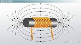
An inductor is a passive electrical component that stores energy in a magnetic field when an electric current flows through it. It is typically made of a coil of insulated wire and opposes any change in the current passing through it, a property known as inductance.
Time-Domain Relationships
-
Voltage leads current (because voltage depends on the rate of change of current).
-
Constant current:
-
Sudden current change: large voltage spike
For Sinusoidal signals
Let
Therefore, the current will be:
current lags voltage by
2. Capacitors
A capacitor is an electronic component that stores electrical energy in an electric field, made of two parallel conducting plates separated by an insulating material called a dielectric. When a voltage is applied, it accumulates opposite charges on the plates, and it can release this energy quickly, unlike a battery which releases energy slowly.
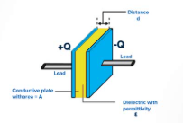
The equation of a capacitor is:
-
Current leads voltage (because current depends on the rate of change of voltage).
-
Constant voltage:
-
Sudden voltage change: large current spike
For sinusoidal signals:
current leads voltage by
Impedance and Reactance
Impedance
- Resistor:
- Inductor:
- Capacitor:
S.I unit: ohms
Reactance
Reactance is the magnitude of impedance (ignoring the sign/phase):
Inductance
Inductance increases with the frequency, since they block high-frequency signals.
S.I unit: ohms
Capacitance
The capacitance of a capacitor decreases with the frequency, since they allow high frequency signals.
Example 1 - Pure Resistor circuit
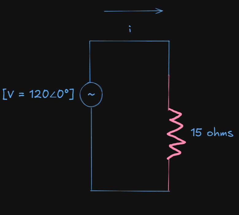
We need to calculate all three types of power and the power factor here as well.
Starting off with the given voltage. When nothing is said about the amplitude type, it's safe to assume that it's RMS.
Given voltage:
Total impedance (
The phase angle
By ohm's law the current will be:
Quick note — about multiplying phasors
- When you multiply two phasors:
However while calculating power:
We use the complex conjugate of the current:
because instantaneous power depends on
In short, while calculating power, subtract the angles.
Remembering our formula table for power:
| Power Type | Symbol | Unit | Formula |
|---|---|---|---|
| Real Power | W (Watts) | ||
| Reactive Power | VAR (Volt-Ampere Reactive) | ||
| Apparent Power | VA (Volt-Ampere) | ||
| Power Factor | - |
Now, let's find out the real power (P) first:
Real power:
(The angle stays the same since
Now, the apparent power(Q):
is also:
Next, the reactive power (S):
Lastly, the power factor:
Since the power factor is 1, it's a purely resistive circuit.
Final answer in time domain:
The instantaneous circuit is:
or:
Example 2 -- Pure Inductor Circuit
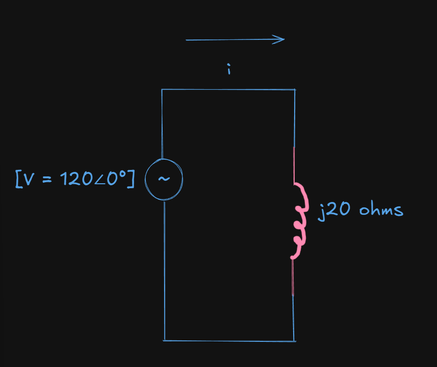
Same voltage, however we have an inductor now of
In inductance terms that would translate to:
This means that the current is lagging behind the voltage by 90 degrees and the voltage is leading ahead of the current by 90 degrees, which is what inductors do.
Now that that's out of the way,
The impedance will be:
Thus the current will be:
Now, for the power calculations
In power calculations, the phase angle always means the phase difference between voltage and current, not their individual phasor angles.
So, here:
So,
This calculated phase angle will be the angle for the voltage, and the current in this power calculation, so we don't need to write them again in the phasor format while calculating.
Real power:
Now, for the apparent power:
Next, for the reactive power:
And the power factor:
which means that this is a purely reactive circuit, no real power consumed. The current just bounces back from the inductor and other sources. All energy is temporarily stored in the inductor’s magnetic field and returned to the source each cycle — no net work is done.
Final instantaneous current in sinusoidal form:
or:
Example 3 -- Pure Capacitor Circuit
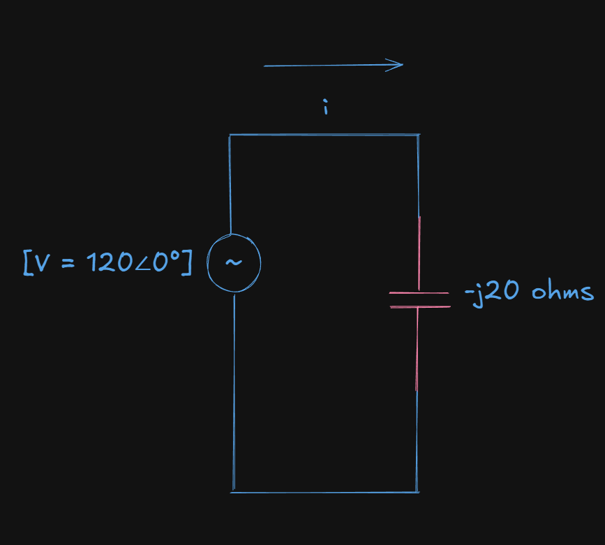
Same voltage, but now we have a capacitor of
which translates to:
This means that the current is leading ahead of the voltage by 90 degrees and the voltage is lagging behind the current by 90 degrees, which is how capacitors work.
So the total impedance, Z, will be:
Thus, the current will be:
Now, for the power calculations:
So,
Real power:
Now, for the apparent power:
You might be concerned as to what's with the negative power here?
Negative reactive power means the circuit is supplying reactive energy back to the source over each cycle (the capacitor charges and discharges), rather than absorbing it. That’s why capacitors are associated with negative
Next, for the reactive power:
And the power factor:
which means that this is a purely reactive circuit, no real power consumed.
Final instantaneous current in sinusoidal form:
or:
Example 4 -- Series RLC circuit
This is the same process, just we have to add up the total impedances.
For parallel impedances:
- Find the reciprocal of each impedance (they are called admittances).
- Convert each admittances to rectangular form and add them up.
- Convert back the total admittance to polar form.
- Get total impedance (
) by inverting this total admittance. - The final impedance angle sign tells you whether the overall network is inductive (+ angle → current lags) or capacitive (− angle → current leads).
The total impedance will be:
The inductance is greater than the capacitance, so the current is lagging behind the voltage (as evidenced by the sign of the phase angle)
This looks like it's a rectangular phasor.
For ease of calculations we need to convert this to a polar phasor.
From:
So,
Thus, the current will be:
So, the current lags behind the voltage by 34.99 degrees
Now, for the power calculations:
So, here:
So,
Real power:
Now, for the apparent power:
Next, for the reactive power:
And the power factor:
Very close to 1, almost purely resistive circuit.
Final instantaneous current in sinusoidal form:
or:
Resonance in single phase AC circuits
In a single-phase AC circuit, resonance occurs when the inductive reactance (
causing the circuit's impedance to be at its minimum and the phase angle between the voltage and current to be zero. This condition results in maximum current flow for a given voltage and causes the circuit to behave like a purely resistive circuit at that specific resonant frequency.
The resonant frequency
It is given by:
Three Phase AC Circuits
A three-phase system consists of three AC voltages of equal magnitude and frequency, but displaced from each other by 120° in phase. This is the standard for power generation and distribution because it's more efficient than single-phase.
Phase sequence: R-Y-B (or A-B-C), meaning voltage in R leads Y by 120°, and Y leads B by 120°.
A better explanation of why 3-phase AC systems are needed
In a single-phase AC system, you have:
-
Two wires: one “live” (carrying alternating voltage) and one “return” (or neutral).
-
The voltage between them is the supply voltage (e.g. 230 V in homes).
-
The current through the wire is the same as the current through the load.
So voltage and current are straightforward — one voltage, one current, one path.
Now imagine a generator that makes three AC voltages
In a three-phase alternator, there are three coils placed 120° apart on the stator.
Each coil produces its own sinusoidal voltage, equal in magnitude but shifted in phase:
In a three-phase alternator, there are three coils placed 120° apart on the stator.
Each coil produces its own sinusoidal voltage, equal in magnitude but shifted in phase.
The Connection Methods
1. Star(Y or Wye) Connection.
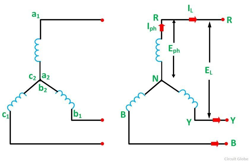
Structure: We tie one end of all three windings together at a common point (called the neutral).
The other ends go out as the line terminals.
Wiring: 4-wire system (3 phase wires + 1 neutral) or 3-wire system (without neutral).
Key Characteristics:
-
Has a neutral point
-
Used for power transmission over long distances
-
Used in low and medium voltage distribution (like household supply - 230V phase, 400V line)
-
3 outer terminals: R, Y, B → called Line wires
-
1 central point: Neutral (N)
Each winding (wire/coil/impedance) (between line and neutral) is a phase.
2. Delta
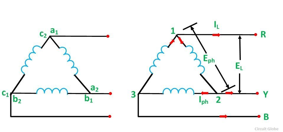
Structure: Three windings are connected in a closed loop (forming a triangle/delta shape).
Wiring: 3-wire system only (no neutral wire).
Key Characteristics:
- No neutral point
- Used for shorter distances
- More common in industrial and high-power applications
No neutral point exists — just three junctions R, Y, B (the lines).
What's Line vs Phase then?
Think of it this way:
| Term | Means (in Star) | Means (in Delta) | Analogy |
|---|---|---|---|
| Phase | Each individual winding of the generator/load (between Line & Neutral). | Each side of the delta loop (between two Lines). | One “sub-circuit” per phase. |
| Line | The external wires that connect the system to the load (R, Y, B). | Same: external wires R, Y, B. | The “mains” wires carrying current to the outside. |
So the phase is an internal quantity (inside the machine or load).
The line is what you can measure from outside — between the terminals.
Final mental picture that should click:
       [ R-phase ] → voltage = 230∠0°
       [ Y-phase ] → voltage = 230∠−120°
       [ B-phase ] → voltage = 230∠−240°
- Each one is its own “phase” (coil or load branch).
- Each produces an AC voltage 120° out of phase with the others.
- The line wires carry those voltages outward.
- The neutral (if star) or shared points (if delta) tie them together electrically.
Voltage and Current Relations
Star Connection
Voltage Relation
where:
is the line voltage (voltage between any two lines) is the phase voltage (voltage between any line and neutral)
Current Relation:
where:
is the line current (current in the line conductor) is the phase current (current through each winding)
Delta Connection
Voltage Relation
Line voltage equals phase voltage.
Current Relation:
Why two kinds of voltages and currents?
It all comes from how the three coils (phases) are connected to the external circuit.
When we join the coils inside the generator or load, some terminals become shared, and some go outward to the lines.
That’s why we end up with:
-
internal quantities → phase voltage/current
-
external, measurable quantities → line voltage/current
Power in Three-Phase Systems
Total Power
For a balanced three-phase system, total power is:
or in terms of line quantities:
Reactive Power
Apparent Power
Power Factor
Practice Numericals
Question 1
A balanced star-connected load has phase voltage of 230V and phase current of 10A with power factor 0.8 lagging. Find: (a) Line voltage, (b) Line current, (c) Total power.
Solution:
Given
(a) Line Voltage:
or:
(b) Line current (in star phase, line current = phase current).
(c) Total power:
Question 2
A balanced delta-connected load draws line current of 20A with line voltage of 400V and power factor 0.9. Find: (a) Phase voltage, (b) Phase current, (c) Total power.
Solution:
Given power factor
(a) Phase voltage: (in delta connection, phase voltage = line voltage)
(b) Phase current:
(c) Total power:
Important Points to Remember
factor: In star, it appears in voltage relation; in delta, it appears in current relation. - Power formula is same for both connections:
- Balanced load: All three phases have equal impedance and equal phase angle.
- Phase sequence: Always assume R-Y-B unless stated otherwise.
- Neutral current in balanced star: Zero (because three equal currents 120° apart cancel out)