Module 3 -- Transformers
Index
- Magnetic Materials and BH Characteristics
- The Electric Transformer
- 1.
Magnetic Field Intensity (the cause) - What exactly is flux?
- 2.
-- Magnetic Flux Density (the effect) - Types of Magnetic Materials
- Ideal Transformer vs Practical Transformer
- Ideal Transformer — The Perfect World
- What are eddy currents?
- Why current goes the opposite way
- Practical Transformer — The Real World
- What actually goes wrong in a real transformer?
- The Two Categories of Loss — Exam Critical
- Regulation, Efficiency, Auto-Transformer and 3-Phase Transformer Connections
- 1. Voltage Regulation
- 2. Efficiency
- 3. Auto Transformer
- Three Phase Transformer
- Transformers Practice Numericals
Magnetic Materials and BH Characteristics
The Electric Transformer
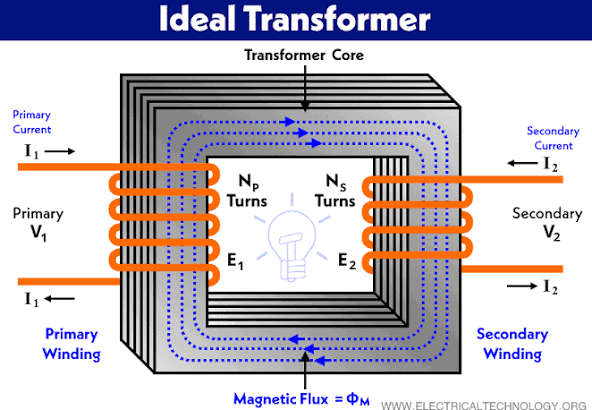
A transformer is a static electrical device that transfers energy between AC circuits through electromagnetic induction, increasing (step-up) or decreasing (step-down) voltage levels without changing frequency. It consists of primary and secondary coils wound around a laminated core, relying on Faraday’s law to induce voltage.
The core idea first: A transformer works by using a changing magnetic field to transfer energy between two coils. So before understanding the transformer itself, you need to understand how materials respond to magnetic fields — that's what BH characteristics describe.
What is a transformer actually trying to do?
It's trying to change voltage levels. That's its entire job.
You feed in AC at one voltage on the primary side, and you get AC out at a different voltage on the secondary side. The question is — how does winding count control this? We will get to this in Ideal Transformer vs Practical Transformer.
Key Quantities
1.
This is what you apply -- it's driven by the current in the coil.
What exactly is flux?
In physics, flux
The Magnetic Flux Intensity is given by:
where:
.
S.I unit:
2.
This is what the material produces in response to
S.I unit:
Here
- Higher permeability = Material is a better conductor of magnetic flux = Magnetic field lines pass through easily.
- Lower permeability = Material is a poorer conductor of magnetic flux = Harder for magnetic field lines to pass through.
Think of H as the "pressure" you're applying, and B as the "flow" you get. The material's permeability is how easily it lets that flow happen — analogous to conductance in electrical circuits.
The B-H Curve (Magnetization Curve)
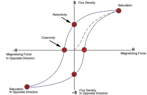
When you plot B (y-axis) vs H (x-axis) for a magnetic material, you don't get a straight line. You get an S-shaped curve, and it tells you three critical things:
1. Linear region — At low H, B increases proportionally. The material is responding normally.
2. Saturation — Beyond a certain H, B stops increasing much even if you push more current. The material is "full" — all magnetic domains are already aligned. This is bad for transformer cores because the inductance drops and the device becomes inefficient.
3. Hysteresis — When you reduce H back to zero, B doesn't go back to zero. Some magnetism remains — called residual magnetism (or remanence). To force B back to zero you need to apply H in the reverse direction. This lag between B and H is called hysteresis.
The area enclosed by the hysteresis loop = energy lost as heat per cycle. This is one of the two core losses in a transformer.
Types of Magnetic Materials
| Type | BH Loop | Use |
|---|---|---|
| Soft magnetic (e.g. silicon steel) | Narrow loop → low hysteresis loss | Transformer cores |
| Hard magnetic (e.g. permanent magnets) | Wide loop → high remanence | Permanent magnets |
Transformer cores use soft magnetic materials precisely because narrow loop = less energy wasted per cycle.
The Connection to Transformers
Here's the link: a transformer core is a magnetic material through which a time-varying flux is constantly cycling B up and down — meaning it's going around the hysteresis loop every single AC cycle (50 times per second at 50 Hz). Every loop = energy lost. This is why core material choice matters enormously.
Ideal Transformer vs Practical Transformer
The Physical Setup First
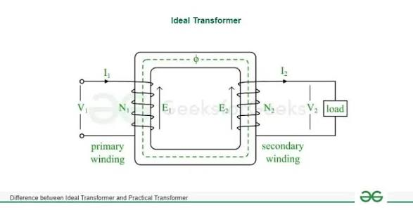
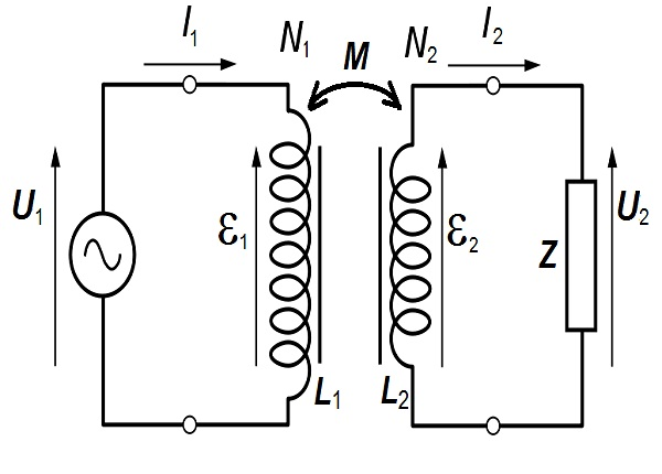
A transformer is two coils (windings) wrapped around a shared magnetic core. The primary winding takes in AC, the changing current creates a changing flux in the core, that flux links to the secondary winding and induces a voltage there. Energy transfers magnetically — no direct electrical connection between the two sides.
This works only with AC — because a steady DC current creates a steady flux, and a steady flux induces nothing. You need change to induce.
Ideal Transformer — The Perfect World
From What is a transformer actually trying to do?
We are trying to understand what the ideal transformer is:
Let's head to the core of the ideal transformer.
Think about what happens in the core. The primary coil has AC flowing through it, which creates a changing flux in the core. That same flux passes through the secondary coil too — they share the core.
Coming to Faraday's law of electromagnetic induction from Module 3 -- Electromagnetism and Dielectric Magnetic properties of materials#Maxwell's Third Equation -- Faraday's Law of Electromagnetic Induction :
Faraday's Law of Electromagnetic Induction states that a changing magnetic field creates an electromotive force (EMF) or voltage in a conductor, which can drive an electric current. The magnitude of this induced EMF is directly proportional to the rate at which the magnetic flux (the amount of magnetic field passing through a loop) changes over time.
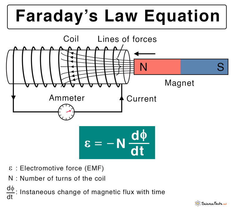
The equation given in the picture is a variation of the Maxwell's third equation, it's specifically for a magnet being moved through a copper coil.
Now, Faraday's law says: every time a flux line cuts through a turn of wire, it induces a small voltage in that turn. So:
- If the secondary coil has more turns than the primary → more turns getting cut by the same flux → higher voltage induced → step-up transformer.
- If the secondary coil has fewer turns → fewer turns cut → lower voltage → step-down transformer.
So voltage is literally proportional to how many turns are "collecting" the flux:
An ideal transformer assumes:
- Zero winding resistance (no copper loss)
- All flux stays in the core — no leakage
- Core has infinite permeability (needs zero H to establish flux)
- No core losses (no hysteresis, no eddy currents)
What are eddy currents?
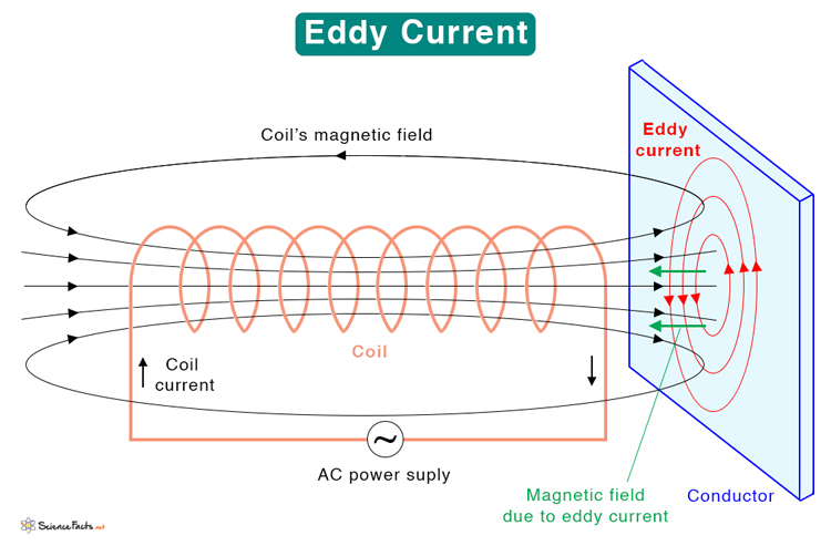
Eddy currents are loops of electrical current induced within conductors by a changing magnetic field or by relative motion between a conductor and a magnetic field. These swirling currents flow in closed loops perpendicular to the magnetic field, generating their own magnetic fields that oppose the original change, in accordance with Lenz's Law, which states that the direction of the induced magnetic field (or EMF) opposes the change that caused the EMF.
Maxwell's third equation in it's proper integral form is:
The negative sign is Lenz's Law.
Eddy currents are undesirable in transformers because they create significant energy losses in the form of heat within the magnetic core. These induced, circulating currents reduce the overall efficiency, cause overheating, and can degrade the transformer's lifespan. They are minimized by using insulated, laminated core plates instead of solid metal. See more in Practical Transformer — The Real World.
Why current goes the opposite way
Here's where conservation of energy comes in. The transformer is ideal — meaning no losses. So:
If you stepped the voltage up
==This is why high-voltage transmission lines carry low current ==— the transformer stepped voltage up enormously, so current dropped enormously, which means much less
Under these assumptions, the entire behaviour collapses into one elegant relationship — the turns ratio:
where
→ step-down (more primary turns, less secondary turns) → step-up (less primary turns, more secondary turns)
And since an ideal transformer conserves power perfectly,
The core intuition: Voltage scales with turns ratio, current scales inversely. Step up voltage → step down current, and vice versa. Power is conserved.
Practical Transformer — The Real World
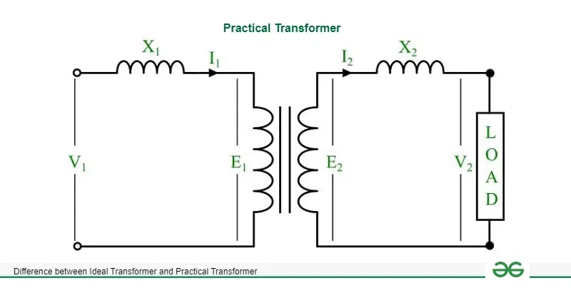
What actually goes wrong in a real transformer?
Ask yourself: in the ideal transformer, we assumed nothing gets wasted and everything is perfect. In reality, two physical things fight against that:
The wire has resistance. And the core isn't perfect.
That's genuinely it. Everything in the practical transformer model comes from just these two physical facts.
Problem 1 — The wire has resistance
The coils are made of copper wire, and copper has resistance. So when current flows through the primary winding, some voltage is dropped across that resistance before it even reaches the "transformer action" part. Same on the secondary side — the output voltage gets slightly reduced by the resistance of the secondary winding.
This is called copper loss — energy wasted as heat in the windings, just like any resistor. More current drawn by the load → more heat wasted.
Also, not all the flux created by the primary stays neatly inside the core. Some of it "leaks" out through the air and never reaches the secondary. This leakage flux doesn't contribute to voltage transfer — it just acts like a stray inductance in series, slightly opposing current flow.
Problem 2 — The core isn't perfect
Two things happen inside the core:
Hysteresis — you already know this. The core cycles around the BH loop 50 times per second, losing energy as heat each time.
Eddy currents — Covered in What are eddy currents?.
Both of these are core losses — and crucially, they happen regardless of whether you've connected any load. As long as the transformer is plugged in and AC is running through the primary, the core is cycling and losing energy.
So how do we model this?
Here's the key insight — every imperfection maps to a circuit element:
==The winding resistance → a resistor in series ==(it drops voltage proportional to current). (
==The leakage flux → an inductor in series ==(it opposes changing current). This leakage acts like an inductance in series — called leakage reactance (
The core loss → a resistor in parallel (it draws a small constant current to account for the energy being lost in the core, regardless of load)
The magnetizing effect → an inductor in parallel (some current is always needed just to maintain the flux in the core, even at no load — this is the magnetizing current)
So the practical transformer equivalent circuit is just the ideal transformer with these four elements added around it. The series elements on each side account for winding imperfections. The parallel branch accounts for core imperfections.
The "tax" analogy
In the ideal transformer, 100% of input power reaches the output. In the practical transformer, power gets "taxed" twice:
Core loss tax — paid just for being switched on (constant, load-independent)
Copper loss tax — paid based on how much current you draw (load-dependent)
The Two Categories of Loss — Exam Critical
| Loss | Cause | Varies with? |
|---|---|---|
| Copper loss ( |
Winding resistance | Load current (load-dependent) |
| Core loss (hysteresis + eddy current) | Core material & flux | Supply voltage & frequency (load-independent) |
Regulation, Efficiency, Auto-Transformer and 3-Phase Transformer Connections
1. Voltage Regulation
What it's asking: How much does the output voltage drop when you connect a load, compared to when nothing is connected?
An ideal transformer — no drop at all. Practical transformer — the series resistances and leakage reactances cause a voltage drop under load, so the secondary voltage sags below what it was at no load.
where
A good transformer has low regulation — meaning output voltage stays stable regardless of load. Ideally 0%.
2. Efficiency
Transformer efficiency is the ratio of output power to input power, representing how effectively a transformer converts energy, typically operating at high efficiencies of 97% to 99%.
The two losses in the denominator are exactly the two taxes we discussed earlier.
Maximum efficiency occurs when:
Core loss is fixed (always on). Copper loss increases with load. At light load, copper loss is tiny but core loss dominates, so efficiency is low. At heavy load, copper loss dominates and grows rapidly. The sweet spot — maximum efficiency — is exactly where they're equal, because that's where the total loss is minimized relative to output power.
3. Auto Transformer

An auto transformer is an electrical transformer with a single continuous winding that acts as both the primary and secondary, connected both magnetically and electrically. It is used to efficiently step up or step down AC voltages, offering higher efficiency, lower cost, smaller size, and better regulation compared to two-winding transformers.
The regular transformer has two separate, isolated windings. The auto-transformer uses one single winding with a tap taken partway along it. Part of the winding serves as both primary and secondary simultaneously.
Advantage: More efficient, smaller, lighter — because part of the power is transferred conductively (direct electrical connection) rather than purely magnetically. Less copper needed.
Disadvantage: No electrical isolation between primary and secondary. In a regular transformer, the two sides are magnetically coupled but electrically isolated — a safety feature. The auto-transformer loses this, which limits its use in safety-critical applications.
Use cases: Variable voltage supplies (like a variac), motor starters, and situations where isolation isn't required but size/weight matters.
Three Phase Transformer
A 3-phase transformer is an electrical device used to step up or step down voltage in three-phase AC power systems, crucial for efficient electricity generation, transmission, and distribution. They can be constructed as a single unit on a common core or as a bank of three single-phase transformers. Common configurations include Delta-Delta, Wye-Wye, Delta-Wye, and Wye-Delta
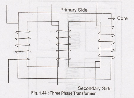
| Configuration | Primary | Secondary | Use Case |
|---|---|---|---|
| Star | Star | High voltage transmission | |
| Star | Delta | Step-down (transmission to distribution) | |
| Delta | Star | Step-up (generator to transmission) | |
| Delta | Delta | Industrial, no neutral needed |