Module 5 -- Power Converters
Index
- DC-DC Converters and Duty Ratio
- Buck Converter -- Step Down DC
- Boost Converter -- Step Up DC
- Inverters and Sinusoidal PWM
- The H-Bridge — How Switching Creates AC
- Sinusoidal PWM — Making a Proper Sine Wave
- Single-Phase vs Three-Phase Inverters
- Practice Numericals
DC-DC Converters and Duty Ratio
Everything in Unit 5 is about converting electrical power from one form to another efficiently. Two conversion problems:
DC → DC at a different voltage level (buck/boost converters) DC → AC (inverters)
Notice — this is the power electronics answer to the same problem transformers solve, but for DC. Transformers can't work on DC (no changing flux), so we need a completely different approach. That approach is switching.
The Core Idea: Switching
Instead of wasting excess voltage as heat (like a resistor would), a switching converter rapidly turns a switch ON and OFF. By controlling how long the switch stays on vs off, you control how much energy gets through — and therefore the output voltage. This is far more efficient than resistive voltage division.
The key parameter controlling this is the duty ratio (D):
where
Think of it like a tap that opens and closes rapidly — the duty ratio is the fraction of time the tap is open. The longer it stays open per cycle, the more water (energy) gets through.
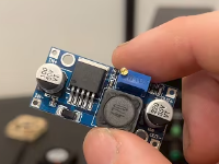
Buck Converter -- Step Down DC
https://www.youtube.com/watch?v=rfChSvb8FX0
Job: Take a higher DC voltage in, deliver a lower DC voltage out.
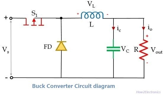
Key components: A switch (transistor), a diode, an inductor, and a capacitor.
How it works conceptually:
- Switch ON → input voltage drives current through the inductor to the load. The inductor stores energy.
- Switch OFF → inductor releases its stored energy to keep current flowing to the load (through the diode). Output capacitor smooths the voltage.
The inductor is the hero here — it resists sudden changes in current, so it acts as an energy buffer, smoothing out the choppy switching into a steady DC output.
Output voltage:
Since
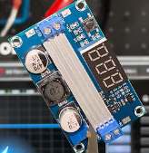
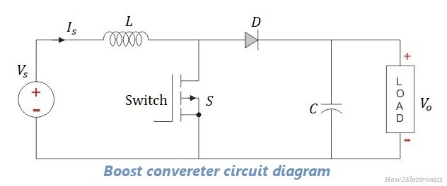
Boost Converter -- Step Up DC
https://www.youtube.com/watch?v=9QM55r5fnUk
Job: Take a lower DC voltage in, deliver a higher DC voltage out.
How it works conceptually:
-
Switch ON → current flows through the inductor, building up a magnetic field. The diode blocks current from reaching the output, so the capacitor supplies the load alone.
-
Switch OFF → the inductor's collapsing magnetic field generates a voltage in addition to the supply voltage. This combined voltage charges the capacitor and supplies the load — at a higher level than the input.
The inductor here acts like a spring — you compress it (store energy) when the switch is on, then it kicks back with extra force when released.
Output voltage:
Since
Buck vs Boost — Side by Side
| Buck Converter | Boost Converter | |
|---|---|---|
| Function | Step down DC | Step up DC |
| Output Voltage | ||
| D effect | Higher |
Higher |
| Analogy | Tap controlling flow | Spring storing then releasing |
Note both converters increase output voltage by increasing D — the difference is just the mechanism and the direction of conversion.
Inverters and Sinusoidal PWM
https://www.youtube.com/watch?v=lHWmh0Bc83g
The Problem Inverters Solve
Buck and boost converters deal with DC→DC. But what if you have DC (like a battery or solar panel) and need AC to power normal household or industrial equipment? That's what an inverter does — DC in, AC out.
The core challenge: how do you make AC from DC using switches? You can't just flip a switch once — you need a controlled, repeating pattern that mimics a sine wave.
The H-Bridge — How Switching Creates AC
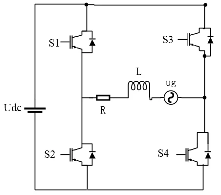
The fundamental inverter circuit is an H-bridge — four switches arranged so that by turning specific pairs on and off, you can force current through the load in alternating directions.
- Switches S1 and S4 ON → current flows left to right through load → positive half cycle
- Switches S2 and S3 ON → current flows right to left through load → negative half cycle
Alternate these pairs at the desired AC frequency (say 50 Hz) and you get a square wave AC output. That's the basic idea — but a square wave isn't a sine wave. This is where PWM comes in.
Sinusoidal PWM — Making a Proper Sine Wave
PWM stands for Pulse Width Modulation. The idea is elegant:
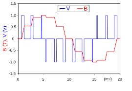
Instead of switching at a fixed duty ratio, you vary the duty ratio continuously in a pattern that follows a sine wave. Rapid pulses with varying widths — wide pulses where the sine wave should be large, narrow pulses where it should be small.
The load (especially if it has inductance, like a motor) naturally filters out the high-frequency switching and responds only to the average — which, if the pulse widths were varied sinusoidally, is a sine wave.
How it's generated: Two signals are compared:
- A reference sine wave at the desired output frequency (e.g. 50 Hz) — this is what you want the output to look like
- A high-frequency triangular carrier wave (e.g. 5000 Hz) — this is the switching clock
When the sine wave is above the triangular carrier → switch ON. When below → switch OFF. The result is a series of pulses whose widths naturally follow the sine shape.
- m = 1 → full sine wave output
- m < 1 → reduced amplitude output
- m > 1 → overmodulation, distortion begins
Single-Phase vs Three-Phase Inverters
Single-phase inverter — A single-phase inverter converts DC source voltage (from batteries or solar panels) into a 220V/110V single-phase AC output for home/office appliances. Utilizing bridge circuits, they produce a sinusoidal waveform to power single-phase loads. One H-bridge, produces one AC output. Used in small UPS systems, solar inverters for homes.
Three-phase inverter — A three-phase inverter is a power electronics device that converts DC power (from solar panels, batteries) into three-phase AC power, featuring three 120-degree phase-shifted outputs. It uses six switches (IGBTs/MOSFETs) arranged in three legs to produce high-efficiency AC power for industrial motor drives, HVDC systems, and large-scale solar installations. Three H-bridges sharing the same DC bus, each producing a sine wave shifted 120° from the others. Exactly replicating the three-phase AC system from Unit 2.
The same PWM principle applies to three-phase — just three reference sine waves, each 120° apart, compared against the same triangular carrier.
The Full Unit 5 Story Connected
DC source → need lower DC voltage → Buck converter (D controls step-down)
DC source → need higher DC voltage → Boost converter (D controls step-up)
DC source → need AC → Inverter (H-bridge switching) → shaped by Sinusoidal PWM → clean sine wave output → single or three-phase depending on application
All three are fundamentally the same idea: controlled switching doing what resistors and transformers can't — converting power efficiently without wasting it as heat.