Module 1 -- Computer Networks
Index
- What is a Computer Network?
- Types of Topologies in Computer Networks
- 1. Point-to-Point Topology
- 2. Mesh Topology
- 3. Star Topology
- 5. Ring Topology
- 6. Tree Topology
- 7. Hybrid Topology
- Protocols used in Computer Networks
- 1. Hypertext Transfer Protocol(HTTP)
- 2. Transmission Control Protocol (TCP)
- Manchester encoding vs Differential Manchester Encoding
- The OSI Model
- Layers of the OSI Model
- Transmission Media
- 1. Guided Media
- 2. Unguided Media
- Devices that work in the layers of the OSI Model
- 1. Repeater (Physical Layer)
- 2. Hub (Physical Layer)
- 3. Bridge (Physical and Data Link Layer)
- 4. Switch (Data Link Layer)
- LAN Local Area Network
- Wireless Lan (Wi-Fi or WLAN)
- Connecting LANs
- Virtual LAN (VLAN)
What is a Computer Network?
A computer network is a system of interconnected computing devices that allow them to communicate, share resources, and exchange data using established protocols.
Key Elements:
-
Sender: The device that sends the data.
-
Receiver: The device that receives the data.
-
Medium: The channel through which data is transmitted (e.g., fiber optic cables, radio waves).
-
Message: The actual data being communicated.
-
Protocols: Rules governing data exchange.
-
Types of Networks:
There are various types of computer networks, including:
-
Local Area Network (LAN): Connects devices within a limited geographical area, like a home or office.
-
Wide Area Network (WAN): Connects devices across a large geographical area, like different cities or countries.
-
Metropolitan Area Network (MAN): Connects devices within a metropolitan area.
-
Personal Area Network (PAN): Connects devices within a short range, typically around a person.
-
Types of Topologies in Computer Networks
Connection Topologies
- Definition: The physical or logical layout of devices in a network.
- Common Topologies:
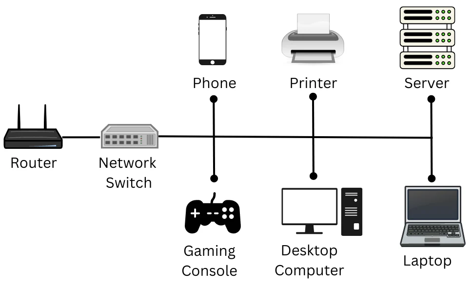
- Bus Topology: All devices share a single communication line.
- Star Topology: All devices are connected to a central hub.
- Ring Topology: Each device is connected to two other devices, forming a ring.
- Mesh Topology: Devices are interconnected with many redundant interconnections.
- Hybrid Topology: Combination of two or more topologies.
https://www.geeksforgeeks.org/types-of-network-topology/
Network topology refers to the arrangement of different elements like nodes, links, or devices in a computer network. Common types of network topology include bus, star, ring, mesh, and tree topologies, each with its advantages and disadvantages. In this article, we will discuss different types of network topology in detail.
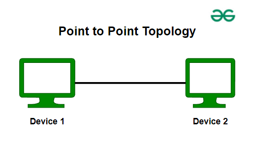
1. Point-to-Point Topology
Point-to-point topology is a type of topology that works on the functionality of the sender and receiver. It is the simplest communication between two nodes, in which one is the sender and the other one is the receiver. Point-to-Point provides high bandwidth.
2. Mesh Topology
In a mesh topology, every device is connected to another device via a particular channel. Every device is connected to another via dedicated channels. These channels are known as links. In Mesh Topology, the protocols used are AHCP (Ad Hoc Configuration Protocols), DHCP (Dynamic Host Configuration Protocol), etc.
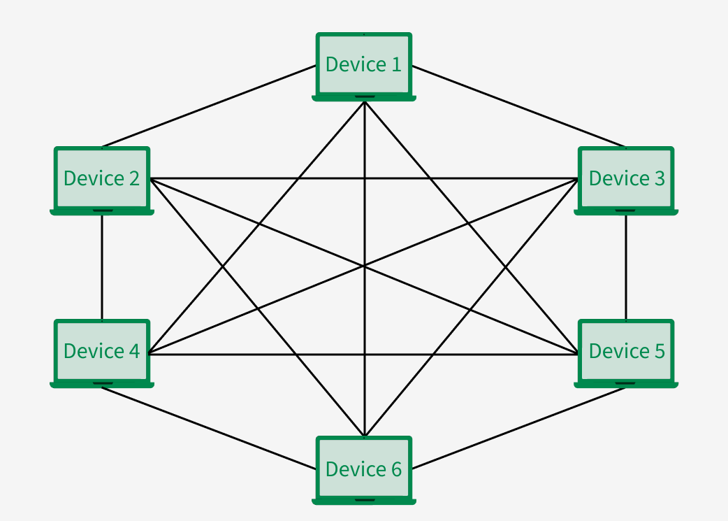
Suppose, the N number of devices are connected with each other in a mesh topology, the total number of ports that are required by each device is N-1.
So if there are 6 devices in this case, each device will need 5 ports.
Advantages of Mesh Topology
- Communication is very fast between the nodes.
- Mesh Topology is robust.
- The fault is diagnosed easily. Data is reliable because data is transferred among the devices through dedicated channels or links.
- Provides security and privacy.
Disadvantages of Mesh Topology
- Installation and configuration are difficult.
- The cost of cables is high as bulk wiring is required, hence suitable for less number of devices.
- The cost of maintenance is high.
A common example of mesh topology is the internet backbone, where various internet service providers are connected to each other via dedicated channels. This topology is also used in military communication systems and aircraft navigation systems.
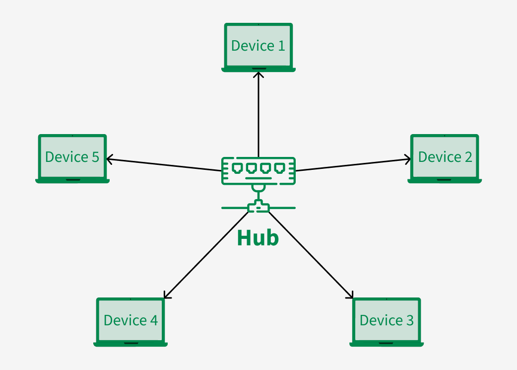
3. Star Topology
In Star Topology, all the devices are connected to a single hub through a cable. This hub is the central node and all other nodes are connected to the central node. The hub can be passive in nature i.e., not an intelligent hub such as broadcasting devices, at the same time the hub can be intelligent known as an active hub. Active hubs have repeaters in them. Coaxial cables or RJ-45 cables are used to connect the computers. In Star Topology, many popular Ethernet LAN protocols are used as CD(Collision Detection), CSMA (Carrier Sense Multiple Access), etc.
Advantages of Star Topology
- If N devices are connected to each other in a star topology, then the number of cables required to connect them is N. So, it is easy to set up.
- Each device requires only 1 port i.e. to connect to the hub, therefore the total number of ports required is N.
- It is Robust. If one link fails only that link will affect and not other than that.
- Easy to fault identification and fault isolation.
- Star topology is cost-effective as it uses inexpensive coaxial cable.
Disadvantages of Star Topology
- If the concentrator (hub) on which the whole topology relies fails, the whole system will crash down.
- The cost of installation is high.
- Performance is based on the single concentrator i.e. hub.
A common example of star topology is a local area network (LAN) in an office where all computers are connected to a central hub. This topology is also used in wireless networks where all devices are connected to a wireless access point.
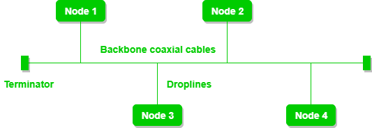
4. Bus Topology
Bus Topology is a network type in which every computer and network device is connected to a single cable. It is bi-directional. It is a multi-point connection and a non-robust topology because if the backbone fails the topology crashes. In Bus Topology, various MAC (Media Access Control) protocols are followed by LAN ethernet connections like TDMA, Pure Aloha, CDMA, Slotted Aloha, etc.
Advantages of Bus Topology
- If N devices are connected to each other in a bus topology, then the number of cables required to connect them is 1, known as backbone cable, and N drop lines are required.
- Coaxial or twisted pair cables are mainly used in bus-based networks that support up to 10 Mbps.
- The cost of the cable is less compared to other topologies, but it is used to build small networks.
- Bus topology is familiar technology as installation and troubleshooting techniques are well known.
- CSMA is the most common method for this type of topology.
Disadvantages of Bus Topology
- A bus topology is quite simpler, but still, it requires a lot of cabling.
- If the common cable fails, then the whole system will crash down.
- If the network traffic is heavy, it increases collisions in the network. To avoid this, various protocols are used in the MAC layer known as Pure Aloha, Slotted Aloha, CSMA/CD, etc.
- Adding new devices to the network would slow down networks.
- Security is very low.
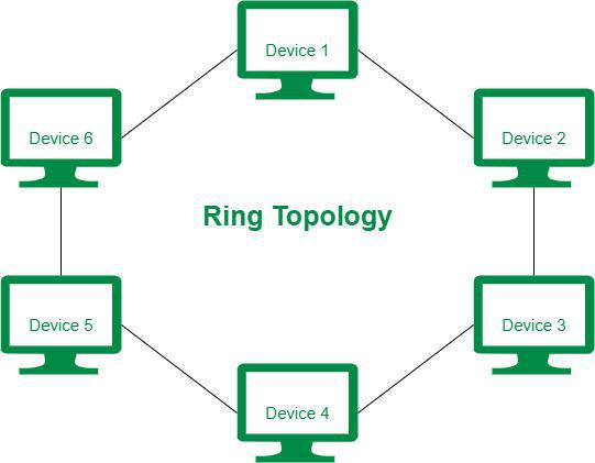
5. Ring Topology
In a Ring Topology, it forms a ring connecting devices with exactly two neighboring devices. A number of repeaters are used for Ring topology with a large number of nodes, because if someone wants to send some data to the last node in the ring topology with 100 nodes, then the data will have to pass through 99 nodes to reach the 100th node. Hence to prevent data loss repeaters are used in the network.
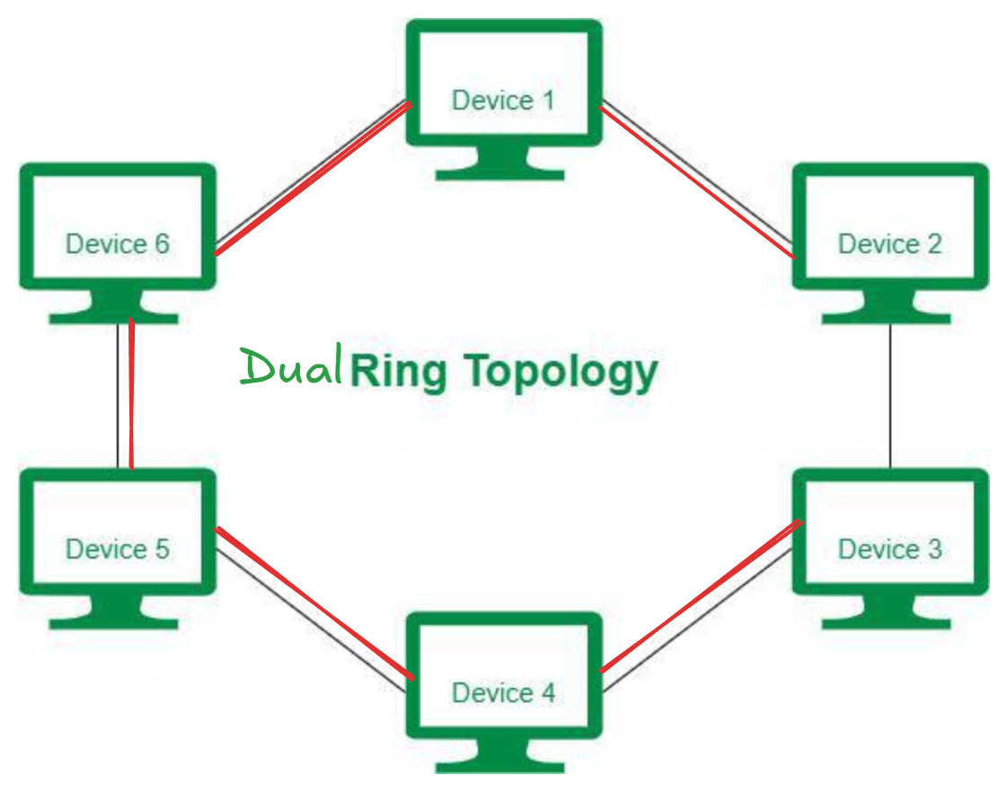
The data flows in one direction, i.e. it is unidirectional, but it can be made bidirectional by having 2 connections between each Network Node, it is called Dual Ring Topology. In-Ring Topology, the Token Ring Passing protocol is used by the workstations to transmit the data.
The most common access method of ring topology is token passing.
- Token passing: It is a network access method in which a token is passed from one node to another node.
- Token: It is a frame that circulates around the network.
Advantages of Ring Topology
- The data transmission is high-speed.
- The possibility of collision is minimum in this type of topology.
- Cheap to install and expand.
- It is less costly than a star topology.
Disadvantages of Ring Topology
- The failure of a single node in the network can cause the entire network to fail.
- Troubleshooting is difficult in this topology.
- The addition of stations in between or the removal of stations can disturb the whole topology.
- Less secure.
6. Tree Topology
Tree topology is the variation of the Star topology. This topology has a hierarchical flow of data. In Tree Topology, protocols like DHCP and SAC (Standard Automatic Configuration) are used.
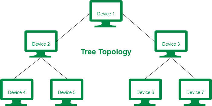
In tree topology, the various secondary hubs are connected to the central hub which contains the repeater. This data flow from top to bottom i.e. from the central hub to the secondary and then to the devices or from bottom to top i.e. devices to the secondary hub and then to the central hub. It is a multi-point connection and a non-robust topology because if the backbone fails the topology crashes.
Advantages of Tree Topology
- It allows more devices to be attached to a single central hub thus it decreases the distance that is traveled by the signal to come to the devices.
- It allows the network to get isolated and also prioritize from different computers.
- We can add new devices to the existing network.
- Error detection and error correction are very easy in a tree topology.
Disadvantages of Tree Topology
- If the central hub gets fails the entire system fails.
- The cost is high because of the cabling.
- If new devices are added, it becomes difficult to reconfigure.
A common example of a tree topology is the hierarchy in a large organization. At the top of the tree is the CEO, who is connected to the different departments or divisions (child nodes) of the company. Each department has its own hierarchy, with managers overseeing different teams (grandchild nodes). The team members (leaf nodes) are at the bottom of the hierarchy, connected to their respective managers and departments.
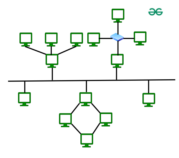
7. Hybrid Topology
Hybrid Topology is the combination of all the various types of topologies we have studied above. Hybrid Topology is used when the nodes are free to take any form. It means these can be individuals such as Ring or Star topology or can be a combination of various types of topologies seen above. Each individual topology uses the protocol that has been discussed earlier.
Advantages of Hybrid Topology
- This topology is very flexible .
- The size of the network can be easily expanded by adding new devices.
Disadvantages of Hybrid Topology
- It is challenging to design the architecture of the Hybrid Network.
- Hubs used in this topology are very expensive.
- The infrastructure cost is very high as a hybrid network requires a lot of cabling and network devices .
A common example of a hybrid topology is a university campus network. The network may have a backbone of a star topology, with each building connected to the backbone through a switch or router. Within each building, there may be a bus or ring topology connecting the different rooms and offices. The wireless access points also create a mesh topology for wireless devices. This hybrid topology allows for efficient communication between different buildings while providing flexibility and redundancy within each building.
Protocols used in Computer Networks
-
Protocols:
- They are sets of rules that determine how data is transmitted and received.
- Examples include TCP/IP, HTTP, FTP, etc.
-
Standards:
- Developed by organizations like IEEE and ITU.
- Ensure compatibility and interoperability between different devices and networks.
- Examples: IEEE 802.3 (Ethernet), IEEE 802.11 (Wi-Fi).
https://www.geeksforgeeks.org/types-of-network-protocols-and-their-uses/
How do Network Protocols Work?
It is essential to understand how devices communicate over a network by recognizing network protocols. The Open Systems Interconnection (OSI), the most widely used model, illustrates how computer systems interact with one another over a network. The communication mechanism between two network devices is shown by seven different layers in the OSI model. Every layer in the OSI model works based on different network protocols. At every layer, one or more protocols are there for network communication. To enable network-to-network connections, the Internet Protocol (IP), for instance, routes data by controlling information like the source and destination addresses of data packets. It is known as a network layer protocol.
(We will study OSI model after this section)
Types of Network Protocols
In most cases, communication across a network like the Internet uses the OSI model. The OSI model has a total of seven layers. Secured connections, network management, and network communication are the three main tasks that the network protocol performs. The purpose of protocols is to link different devices.
The protocols can be broadly classified into three major categories:
- Network Communication
- Network Management
- Network Security
In module 1 we will only study the protocols related to Network Communication.
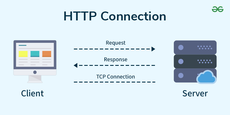
1. Hypertext Transfer Protocol(HTTP)
HTTP stands for “Hypertext Transfer Protocol.” It is a set of rules for sharing data on the World Wide Web (WWW). HTTP helps web browsers and servers communicate, allowing people to access and share information over the internet.
Key Points
- Basic Structure: HTTP forms the foundation of the web, enabling data communication and file sharing.
- Web Browsing: Most websites use HTTP, so when you click on a link or download a file, HTTP is at work.
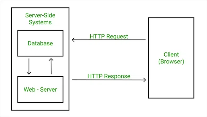
- Client-Server Model: HTTP works on a request-response system. Your browser (client) asks for information, and the website’s server responds with the data.
- Application Layer Protocol: HTTP operates within the Internet Protocol Suite, managing how data is transmitted and received.
What is HyperText?
Data such as text, images, and other multimedia files are shared on the World Wide Web.
Working of HTTP
First of all, whenever we want to open any website we first open a web browser after that we will type the URL of that website (e.g., www.facebook.com ). This URL is now sent to the Domain Name Server (DNS). Then DNS first checks records for this URL in their database, and then DNS will return the IP address to the web browser corresponding to this URL. Now the browser is able to send requests to the actual server.
After the server sends data to the client, the connection will be closed. If we want something else from the server we should have to re-establish the connection between the client and the server.
What is an HTTP Request?
HTTP request is simply termed as the information or data that is needed by Internet browsers for loading a website. This is simply known as HTTP Request.
There is some common information that is generally present in all HTTP requests. These are mentioned below.
- HTTP Version
- URL
- HTTP Method
- HTTP Request Headers
- HTTP Body
HTTP Request Headers
HTTP Request Headers generally store information in the form of key-value and must be present in each HTTP Request. The use of this Request Header is to provide core information about the client’s information, etc.
HTTP Request Body
HTTP Request Body simply contains the information that has to be transferred. HTTP Request has the information or data to be sent to these browsers.
What is HTTP Response?
HTTP Response is simply the answer to what a Server gets when the request is raised. There are various things contained in HTTP Response, some of them are listed below.
- HTTP Status Code
- HTTP Headers
- HTTP Body
HTTP Response Headers
HTTP Response headers are simply like an HTTP Request where it has that work to send some important files and data to the HTTP Response Body.
HTTP Response Body
HTTP Responses are the responses that are received successfully upon the request. Generally, it comes under the requests generated by the web. In most cases, the request is to transfer the HTML data into a webpage.
What is an HTTP Status Code?
HTTP Status Codes are the 3-digit codes that tell the message or simply tell us about the HTTP Request whether it has been completed or not. There are simply 5 types of status codes.
- Informational
- Successful
- Re-directional
- Client-Error
- Server-Error
2. Transmission Control Protocol (TCP)
The TCP/IP model is a fundamental framework for computer networking. It stands for Transmission Control Protocol/Internet Protocol, which are the core protocols of the Internet. This model defines how data is transmitted over networks, ensuring reliable communication between devices. It consists of four layers: the Link Layer, the Internet Layer, the Transport Layer, and the Application Layer. Each layer has specific functions that help manage different aspects of network communication, making it essential for understanding and working with modern networks.
What Does TCP/IP Do?
The main work of TCP/IP is to transfer the data of a computer from one device to another. The main condition of this process is to make data reliable and accurate so that the receiver will receive the same information which is sent by the sender. To ensure that, each message reaches its final destination accurately, the TCP/IP model divides its data into packets and combines them at the other end, which helps in maintaining the accuracy of the data while transferring from one end to another end.
Difference Between TCP and IP
| Feature | TCP (Transmission Control Protocol) | IP (Internet Protocol) |
|---|---|---|
| Purpose | Ensures reliable, ordered, and error-checked delivery of data between applications. | Provides addressing and routing of packets across networks. |
| Type | Connection-oriented | Connectionless |
| Function | Manages data transmission between devices, ensuring data integrity and order. | Routes packets of data from the source to the destination based on IP addresses. |
| Error Handling | Yes, includes error checking and recovery mechanisms. | No, IP itself does not handle errors; relies on upper-layer protocols like TCP. |
| Flow Control | Yes, includes flow control mechanisms. | No |
| Congestion Control | Yes, manages network congestion. | No |
| Data Segmentation | Breaks data into smaller packets and reassembles them at the destination. | Breaks data into packets but does not handle reassembly. |
| Header Size | Larger, 20-60 bytes | Smaller, typically 20 bytes |
| Reliability | Provides reliable data transfer | Does not guarantee delivery, reliability, or order. |
| Transmission Acknowledgment | Yes, acknowledges receipt of data packets. | No |
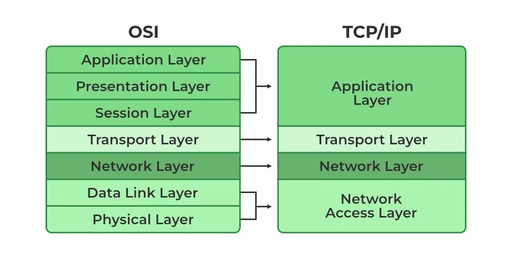
Layers of TCP/IP Model
- Application Layer
- Transport Layer(TCP/UDP)
- Network/Internet Layer(IP)
- Network Access Layer
OSI vs TCP
More protocols are on https://www.geeksforgeeks.org/types-of-network-protocols-and-their-uses/
Manchester encoding vs Differential Manchester Encoding
https://www.youtube.com/watch?v=3IaB2a8tXLA&list=PLxCzCOWd7aiGFBD2-2joCpWOLUrDLvVV_&index=8
Manchester Encoding
Manchester encoding is a method of data transmission used in computer networks and telecommunications. It works by combining the clock and data signals into one stream, making it easier to synchronize the data. Each bit of data is represented by a transition; a change from high to low or low to high in the signal. This helps ensure that the data is correctly interpreted by the receiving device. It is widely used in Ethernet technology and other digital communication systems due to its reliability and simplicity.
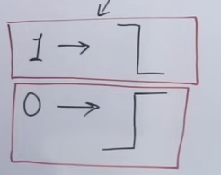
This is how 1 and 0 are represented in Dr. Thomas' Manchester Encoding.

And this is how the IEEE 8.02 convention works for Manchester Encoding.
So Manchester Encoding was all about state changes, or vertex points, representing either 1 or 0, depending on the convention.
Differential Manchester Encoding

This is how 1s and 0s are represented in Differential Manchester Encoding.
Differential Manchester encoding works on representing "edge" transitions. That a 1 or 0 is categorized as a signal goes to a high or low, not after it reaches a high or low as it was in the normal Manchester Encoding.
The OSI Model
https://www.geeksforgeeks.org/open-systems-interconnection-model-osi/
The OSI (Open Systems Interconnection) Model is a set of rules that explains how different computer systems communicate over a network. OSI Model was developed by the International Organization for Standardization (ISO). The OSI Model consists of 7 layers and each layer has specific functions and responsibilities. This layered approach makes it easier for different devices and technologies to work together. OSI Model provides a clear structure for data transmission and managing network issues. The OSI Model is widely used as a reference to understand how network systems function.
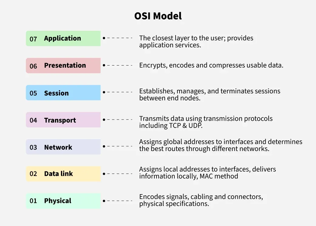
Layers of the OSI Model
There are 7 layers in the OSI Model and each layer has its specific role in handling data. All the layers are mentioned below:
- Physical Layer
- Data Link Layer
- Network Layer
- Transport Layer
- Session Layer
- Presentation Layer
- Application Layer
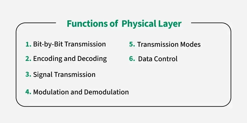
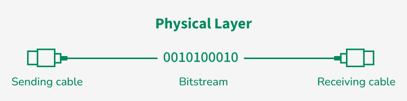
1. Physical Layer
-
Purpose: Deals with the transmission and reception of raw bit streams over a physical medium.
-
Key Responsibilities:
- Signal Transmission: Converts bits into electrical, optical, or radio signals.
- Hardware Components: Defines cables, connectors, hubs, and other physical devices.
- Data Rate & Timing: Manages the bit rate, voltage levels, and synchronization.
-
Examples: Ethernet cables, fiber optics, radio frequencies.
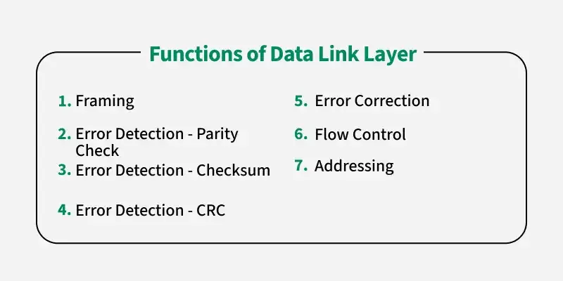
2. Data Link Layer
- Purpose: Provides node-to-node data transfer—a reliable link between two directly connected nodes.
- Key Responsibilities:
- Framing: Organizes raw bits into data frames.
- Error Detection and Correction: Uses techniques like CRC (Cyclic Redundancy Check) to detect and sometimes correct errors.
- Flow Control: Ensures data is sent at a manageable rate.
- MAC (Media Access Control): Determines how devices on the same physical network segment access the medium.
- Examples: Ethernet (IEEE 802.3), Wi-Fi (IEEE 802.11), PPP (Point-to-Point Protocol).
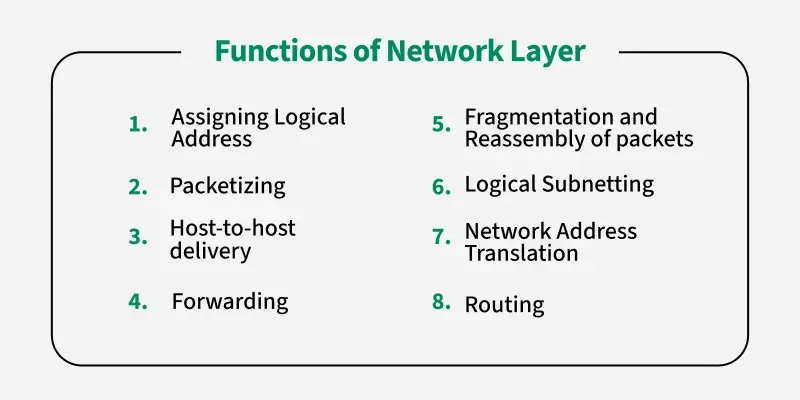
3. Network Layer
- Purpose: Handles the routing of data packets from the source to the destination across multiple networks.
- Key Responsibilities:
- Logical Addressing: Uses IP addresses to uniquely identify devices.
- Routing: Determines the best path for data to travel (using protocols like RIP, OSPF, or BGP).
- Packet Forwarding: Moves packets from one network segment to another.
- Fragmentation and Reassembly: Breaks down large packets and reassembles them at the destination.
- Examples: Internet Protocol (IPv4, IPv6), ICMP (Internet Control Message Protocol).
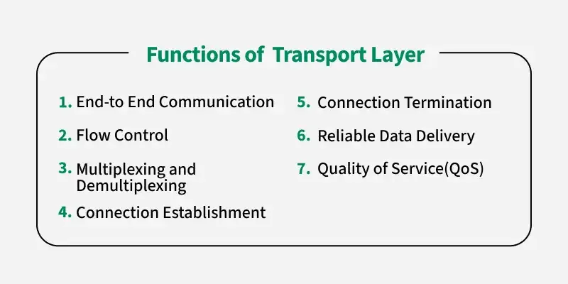
4. Transport Layer
- Purpose: Ensures end-to-end communication and reliability between devices.
- Key Responsibilities:
- Segmentation and Reassembly: Divides data into manageable segments and reassembles them at the destination.
- Error Recovery: Detects errors and requests retransmission if needed.
- Flow Control: Prevents the sender from overwhelming the receiver.
- Connection Management: Offers both connection-oriented (e.g., TCP) and connectionless (e.g., UDP) services.
- Examples: TCP (Transmission Control Protocol) for reliable communication, UDP (User Datagram Protocol) for faster, less reliable data transfer.
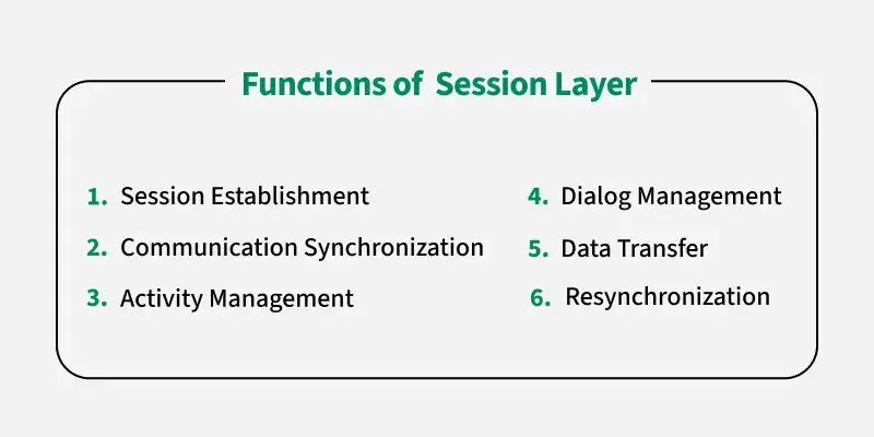
5. Session Layer
- Purpose: Manages sessions or connections between applications.
- Key Responsibilities:
- Session Establishment, Maintenance, and Termination: Sets up, coordinates, and ends communication sessions.
- Dialog Control: Manages who transmits data, and when (e.g., full-duplex vs. half-duplex communication).
- Examples: Protocols and APIs like NetBIOS, RPC (Remote Procedure Call) often incorporate session layer functions.
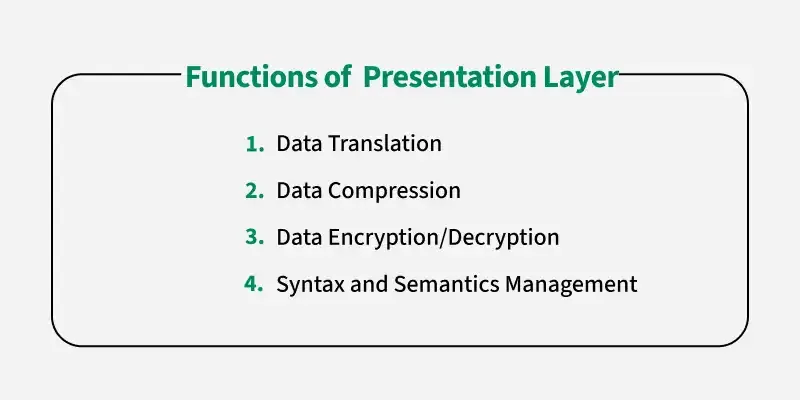
6. Presentation Layer
- Purpose: Acts as a translator between the network and the application, ensuring data is in a usable format.
- Key Responsibilities:
- Data Translation: Converts data formats (e.g., from EBCDIC to ASCII).
- Encryption and Decryption: Ensures data security during transmission.
- Compression: Reduces the size of data to optimize transmission.
- Examples: Encryption protocols (SSL/TLS), data format standards like JPEG, MPEG, or ASCII.
7. Application Layer
-
Purpose: Serves as the interface between the end user and the network.
-
Key Responsibilities:
- Providing Network Services: Offers services directly to user applications.
- User Interface: Facilitates communication through software applications.
- Protocol Handling: Manages protocols that support specific applications such as web browsing, file transfers, or email.
-
Examples: HTTP (Hypertext Transfer Protocol), FTP (File Transfer Protocol), SMTP (Simple Mail Transfer Protocol), DNS (Domain Name System).

How the Layers Work Together
- Encapsulation and Decapsulation: As data moves down from the Application layer to the Physical layer on the sender’s side, each layer adds its own header (and sometimes a trailer). On the receiving side, each layer strips off its respective header as the data moves up.
- Modularity: Each layer serves a specific function and communicates with the layers directly above and below it. This modularity allows for troubleshooting and protocol design to be more efficient.
- Interoperability: The model provides a universal language for networking, making it easier for different systems and technologies to communicate.
Devices that work in the layers of the OSI Model
1. Repeater (Physical Layer)
https://www.youtube.com/watch?v=mf4bRP_puNQ&list=PLxCzCOWd7aiGFBD2-2joCpWOLUrDLvVV_&index=11
1. Role and Operation at the Physical Layer
-
Physical Layer Device:
Repeaters are hardware devices that operate at the physical layer of the OSI model. This means they deal solely with the electrical or optical signals rather than with data formats, addressing, or error checking, which are managed by higher layers like the data link layer (which handles MAC addresses) or the network layer (which deals with IP addresses). -
No Data-Link or Network Intelligence:
Since repeaters do not operate at the data link or network layers, they cannot inspect or filter packets based on MAC or IP addresses. Their function is limited to handling raw signals without understanding the content or the destination.
2. Purpose of Using Repeaters
-
Combating Attenuation:
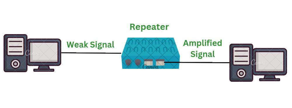
In any transmission medium (e.g., coaxial cables like those used in 10Base2 networks), the signal loses strength (attenuates) as it travels. For instance, a typical 10Base2 cable might only support a 200-meter length before the signal degrades.- Attenuation Problem: Without intervention, the weakened signal would eventually become too corrupted to be useful.
- Repeater’s Role: A repeater regenerates the signal to its original strength, allowing it to travel further without corruption.
-
Extending Transmission Distance:
By placing a repeater between two cable segments, the maximum distance the signal can cover is effectively doubled. In the example given, a 200-meter segment becomes 400 meters when a repeater is used.
3. Difference Between a Repeater and an Amplifier
-
Repeater:
- Signal Regeneration: The repeater receives the incoming digital signal and reconstructs it bit by bit. It regenerates the signal to match the original voltage and form, effectively “cleaning” up any degradation that occurred due to attenuation.
- Preservation of Signal Quality: It ensures that the regenerated signal is a faithful reproduction of the original signal.
-
Amplifier:
- Signal Boosting: An amplifier simply increases the strength (voltage) of the degraded signal without necessarily reconstructing the exact original waveform.
- Potential for Noise Amplification: While it boosts the signal, any noise or distortions present in the signal are also amplified, which can lead to further degradation in quality if not managed properly.
4. Characteristics of Repeaters
-
Two-Port Device:
A typical repeater has two ports – one for receiving the weakened signal and another for transmitting the regenerated signal. This simplicity underscores its function as a point-to-point link extender. -
Forwarding Function:
- Simple Forwarding: The repeater simply forwards every incoming signal from one port to the other. There is no decision-making process to filter or block signals based on any criteria.
-
Lack of Filtering:
- No Selective Transmission: Unlike routers or bridges that can filter traffic (for instance, by preventing local traffic from being unnecessarily transmitted to another network segment), repeaters lack this capability due to their hardware-only design.
- Implication: All signals, regardless of destination, are forwarded to the next segment, which can lead to inefficiencies.
5. Collision Domain Considerations
-
Single Collision Domain:
Since repeaters do not segment the network, all devices connected through a repeater are part of the same collision domain. This means that if multiple devices transmit simultaneously, collisions (overlapping signals) can occur across the entire network segment. -
Buffering:
- Lack of Buffers: The transcript mentions that devices with buffers (used in “store and forward” techniques) can hold incoming data to manage collisions. However, repeaters do not have such buffers.
- Consequence: Without buffering, repeaters forward signals immediately, which means that if multiple signals arrive at the same time, they will collide, potentially resulting in data loss or corruption.
2. Hub (Physical Layer)
https://www.youtube.com/watch?v=3N5a9cHYzCM&list=PLxCzCOWd7aiGFBD2-2joCpWOLUrDLvVV_&index=12
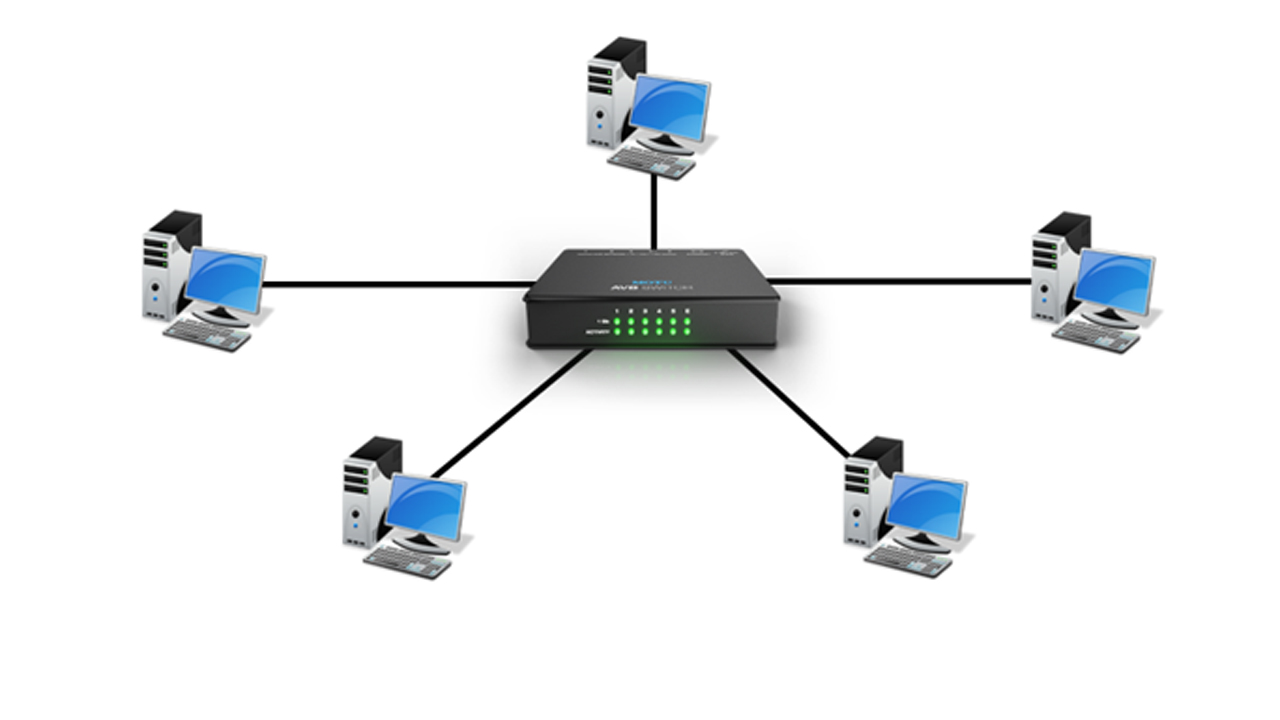
A hub is a basic networking device that, much like a repeater, operates at the physical layer of the OSI model. It’s often described as a "multiport repeater" because its main function is to broadcast signals it receives to all other connected ports. Here’s a detailed breakdown of how a hub works and its role in computer networks:
1. Operating Principle
-
Physical Layer Device:
Just like a repeater, a hub functions at the physical layer. It deals solely with the electrical signals or optical pulses without interpreting the data or examining packet addresses. -
Multiport Repeater:
The hub takes an incoming signal from one port and replicates (or “repeats”) that signal to all of its other ports. Every device connected to the hub receives the transmitted data, regardless of whether it is the intended recipient.
2. How a Hub Works
-
Signal Broadcast:
When a device sends data to the hub, the hub does not perform any filtering or intelligent routing. Instead, it broadcasts the data out through all other connected ports. -
No Data Filtering:
Because hubs are unaware of data-link or network layer protocols (like MAC or IP addresses), they cannot determine the intended destination. Therefore, every packet is sent to every device, which can lead to unnecessary network traffic. -
Collision Domain:
Since the hub broadcasts data to every port, all devices connected to it share the same collision domain. This means that if two devices transmit at the same time, their signals might collide, leading to network inefficiencies.
3. Comparison with Other Devices
-
Hub vs. Switch:
- Hub: Operates at the physical layer, sends incoming data to all ports, and does not manage or filter traffic.
- Switch: Operates at the data link layer, can intelligently forward data only to the intended recipient by using MAC address tables, and effectively reduces collisions by segmenting collision domains.
-
Hub vs. Repeater:
- Repeater: Typically has two ports and is used to extend the reach of a network by regenerating signals over a single connection.
- Hub: Functions as a multiport repeater, allowing multiple devices to connect but still lacking any intelligence in signal routing.
4. Practical Implications and Limitations
-
Simplicity and Cost:
Hubs are simple and inexpensive devices, which made them popular in early networking setups for small networks. -
Performance Issues:
- Network Congestion: Because all traffic is broadcast to every connected device, hubs can lead to significant network congestion as the number of devices increases.
- Security Concerns: Since data is sent to all devices, sensitive information could be intercepted by unintended recipients on the same hub.
- Obsolete Technology: With the advancement of networking technology, hubs have largely been replaced by switches, which offer better performance, more efficient data handling, and enhanced security.
3. Bridge (Physical and Data Link Layer)
https://www.youtube.com/watch?v=dDP36_ZBs6A&list=PLxCzCOWd7aiGFBD2-2joCpWOLUrDLvVV_&index=13
Bridge in Computer Networks
A bridge is a network device that operates at the data link layer (Layer 2) of the OSI model. Unlike hubs and repeaters, which function at the physical layer and do not manage traffic intelligently, a bridge filters, forwards, and manages network traffic based on MAC addresses. This makes bridges a crucial component in improving network efficiency and reducing congestion.
1. What is a Bridge?
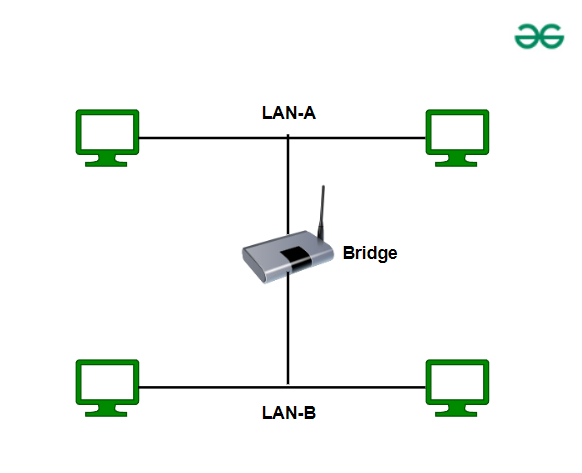
A bridge is a networking device that connects two or more LAN segments and filters traffic based on MAC addresses. Its primary function is to reduce collisions by dividing a single large network into smaller segments.
- It learns the MAC addresses of devices on each segment.
- It decides whether to forward or block traffic based on the destination MAC address.
- Unlike hubs, bridges do not flood the entire network with traffic.
Example Use Case:
Imagine you have two separate LAN segments in an office. Instead of making all devices share the same network (causing collisions and congestion), you can use a bridge to connect them while keeping their traffic separate unless communication is required between the segments.
2. How Does a Bridge Work?
A bridge operates as follows:
-
Listening & Learning (MAC Address Table Building)
- When a bridge is first connected, it operates in a learning mode, where it listens to incoming frames and records the source MAC addresses in a table (MAC Address Table or Filtering Table).
- It keeps track of which MAC address belongs to which network segment.
-
Filtering & Forwarding
- If a frame arrives at the bridge, it checks the destination MAC address:
- If the destination MAC address is in the same segment:
→ The bridge blocks the frame from being forwarded (reducing unnecessary traffic). - If the destination MAC address is in another segment:
→ The bridge forwards the frame only to the required segment.
- If the destination MAC address is in the same segment:
- If a frame arrives at the bridge, it checks the destination MAC address:
-
Broadcast Handling
- Bridges do not filter broadcast traffic (e.g., ARP requests), meaning broadcasts will still reach all devices on connected segments.
3. Types of Bridges
There are different types of bridges based on their functionality:
1. Transparent Bridge
- Also called a learning bridge.
- It operates silently and automatically learns MAC addresses.
- It does not require configuration and simply forwards or filters traffic based on its MAC address table.
- Commonly used in Ethernet networks.
2. Source-Route Bridge
- Used mainly in Token Ring networks.
- It determines the best path for a packet before sending based on the source node’s instructions.
3. Translational Bridge
- Used for converting different network types (e.g., Ethernet to Token Ring).
- Handles format conversion between different networking standards.
4. Difference Between Bridge, Hub, and Switch
| Feature | Hub | Bridge | Switch |
|---|---|---|---|
| OSI Layer | Physical (Layer 1) | Data Link (Layer 2) | Data Link (Layer 2) |
| Traffic Handling | Broadcasts all data | Filters and forwards | Intelligent forwarding |
| MAC Address Learning | No | Yes | Yes |
| Collision Domain | Single | Multiple | Multiple |
| Broadcast Domain | Single | Single | Multiple |
| Speed & Efficiency | Slow (network congestion) | Moderate | Fast (less congestion) |
5. Advantages of a Bridge
✅ Reduces Collisions: By segmenting a network, it prevents unnecessary traffic.
✅ Improves Network Performance: Ensures only necessary traffic is forwarded.
✅ Works Transparently: No need for manual configuration (for transparent bridges).
✅ Connects Different Media Types: Can bridge different network types (e.g., Ethernet to Wi-Fi).
Disadvantages
❌ Cannot Filter Broadcast Traffic: Broadcasts still pass through bridges, potentially causing congestion.
❌ Limited Scalability: Bridges are effective for small networks but can slow down large networks.
❌ Slower than Switches: Bridges process frames using software, whereas switches use hardware (ASICs), making them faster.
6. Real-World Use of Bridges
- Connecting Two Office LANs: If two departments need to be on separate LANs but still communicate, a bridge can connect them efficiently.
- Reducing Network Congestion in Legacy Networks: In older networks where switches are not available, bridges help optimize traffic.
- Wireless Bridge: Used in Wi-Fi networks to extend connectivity across buildings.
4. Switch (Data Link Layer)
https://www.youtube.com/watch?v=vdtqEPKYB5M&list=PLxCzCOWd7aiGFBD2-2joCpWOLUrDLvVV_&index=14
What is a Switch in Networking?
A network switch is a device that operates at the Data Link Layer (Layer 2) of the OSI model and is responsible for efficiently forwarding network traffic based on MAC addresses. Unlike hubs and bridges, which flood traffic across all ports, a switch intelligently directs data only to the intended recipient.
Modern Layer 3 switches also have routing capabilities, allowing them to function like routers by making decisions based on IP addresses.
1. How Does a Switch Work?
A switch functions by learning the MAC addresses of connected devices and directing network traffic efficiently. The process involves:
-
MAC Address Learning
- The switch maintains a MAC Address Table (MAT) (also called a CAM Table).
- It listens to incoming frames and records the source MAC address along with the port it came from.
-
Frame Forwarding
- When a frame arrives at the switch, it checks the destination MAC address:
- If the MAC address is known, it forwards the frame directly to the correct port.
- If the MAC address is unknown, it floods the frame to all ports except the source port (similar to a hub).
- When a frame arrives at the switch, it checks the destination MAC address:
-
Filtering & Collision Prevention
- Unlike a hub, which sends data to all devices, a switch sends it only where needed, reducing collisions.
- Each device connected to a switch gets a dedicated bandwidth, improving performance.
-
Broadcast & Multicast Handling
- Broadcast frames (e.g., ARP requests) are still sent to all devices in the network segment.
- Multicast traffic is handled more efficiently than with hubs or bridges.
2. Types of Switches
Switches can be classified based on functionality and layers of operation.
Based on OSI Layer
| Switch Type | Layer | Function |
|---|---|---|
| Layer 2 Switch | Data Link Layer | Works with MAC addresses, forwards Ethernet frames |
| Layer 3 Switch | Network Layer | Functions like a router, forwards packets based on IP addresses |
| Layer 4-7 Switch (Application Switch) | Transport/Application Layer | Handles QoS (Quality of Service), Load Balancing, and Deep Packet Inspection |
Based on Functionality
| Type | Description |
|---|---|
| Unmanaged Switch | Plug-and-play, no configuration needed, used for small networks |
| Managed Switch | Configurable with VLANs, QoS, SNMP monitoring, used in enterprises |
| Smart Switch | Partially managed, limited settings compared to full-managed switches |
| PoE Switch (Power over Ethernet) | Supplies power to connected devices like IP cameras, VoIP phones, etc. |
| Stackable Switch | Multiple switches act as a single unit, increasing scalability |
| Modular Switch | Expandable with additional network modules |
3. Difference Between Switch, Hub, Bridge, and Router
| Feature | Hub | Bridge | Switch | Router |
|---|---|---|---|---|
| Layer | Physical (Layer 1) | Data Link (Layer 2) | Data Link (Layer 2) | Network (Layer 3) |
| Traffic Handling | Broadcasts all data | Filters & forwards | Intelligent forwarding | Routes packets between networks |
| MAC Address Learning | No | Yes | Yes | No (uses IP addresses) |
| Collision Domain | Single | Multiple | Multiple | Multiple |
| Broadcast Domain | Single | Single | Multiple (if VLANs used) | Multiple |
| Performance | Slow (congestion) | Moderate | Fast | Fastest (for inter-network) |
| Example Use Case | Small home networks | Segmenting networks | Office networks | Connecting different networks (e.g., Internet to LAN) |
4. Advantages of a Switch
✅ Reduces Network Congestion: Unlike hubs, switches send data only to the intended recipient.
✅ Improves Bandwidth Efficiency: Dedicated connections prevent bandwidth sharing.
✅ Supports VLANs (Virtual LANs): Managed switches allow for better network segmentation.
✅ Enhanced Security: Can restrict access and filter MAC addresses.
✅ Full-Duplex Communication: Devices can send and receive data simultaneously, unlike half-duplex hubs.
Disadvantages
❌ Higher Cost: More expensive than hubs and bridges.
❌ Limited to LANs: Switches do not route traffic between different networks (unless using Layer 3 switches).
❌ Configuration Complexity: Managed switches require technical knowledge to set up VLANs and security policies.
5. Use Cases of Switches
-
Enterprise Networks:
- Managed switches are used for efficient data handling.
- VLANs separate departments for security and performance.
-
Data Centers:
- High-performance Layer 3 switches connect multiple servers.
- Load balancing helps optimize server traffic.
-
Home and Small Office Networks:
- Unmanaged switches expand network ports for devices like PCs and printers.
-
VoIP & IP Camera Systems:
- PoE switches power devices like security cameras and VoIP phones.
-
Gaming & High-Speed Networks:
- Switches with low latency ensure fast data transfers for gaming and video streaming.
Router (Physical, Data Link and Network Layer)
https://www.youtube.com/watch?v=JhBnOamc_8s&list=PLxCzCOWd7aiGFBD2-2joCpWOLUrDLvVV_&index=15
A router is a networking device that primarily operates at the Network Layer (Layer 3) of the OSI model, and sometimes even higher layers. Its main purpose is to direct data packets between different networks by determining the best path for the data to travel. Here’s an in-depth explanation of routers and how they function:
1. What is a Router?
-
Network Interconnection:
A router connects multiple networks together—for example, linking a local area network (LAN) to the internet. It functions as a gateway that directs traffic between networks. -
Path Determination:
Routers examine the destination IP address within each packet and use routing tables and protocols (like OSPF, BGP, or RIP) to determine the most efficient path for the data to reach its destination. -
Layer 3 Operations:
Operating at the Network Layer, routers work with IP addresses rather than MAC addresses (which are handled by switches and bridges).
2. How Does a Router Work?
-
Packet Reception:
When a data packet arrives at a router, it is first received on one of the router’s interfaces (ports). -
Header Inspection:
The router reads the packet's header to extract the destination IP address. -
Routing Table Lookup:
Using its routing table, which is a database of possible paths, the router determines the next hop or the best exit interface for forwarding the packet.-
Static Routing: Routes are manually configured by a network administrator.
-
Dynamic Routing: Routes are automatically learned and updated using routing protocols.
-
-
Packet Forwarding:
After determining the optimal path, the router forwards the packet to the next network node or directly to its final destination if it is directly connected. -
Network Address Translation (NAT):
Routers, especially those in home or small office networks, often perform NAT to allow multiple devices with private IP addresses to share a single public IP address for internet access.
3. Types of Routers
-
Core Routers:
Used in the backbone of the internet; they handle very high-speed data transfers between major networks. -
Edge Routers:
Positioned at the edge of networks, they connect internal networks to external networks like the internet. -
Wireless Routers:
Common in home and small office environments; they combine routing functions with wireless access point capabilities. -
Virtual Routers:
Software-based routers that perform routing functions on virtualized platforms or within cloud environments.
4. Key Functions and Features
-
Inter-Network Communication:
Routers ensure that data packets can travel across different networks with varied architectures and technologies. -
Security:
Many routers incorporate built-in firewalls, VPN support, and access control lists (ACLs) to protect networks from unauthorized access. -
Quality of Service (QoS):
Routers can manage and prioritize traffic, ensuring that critical services (like VoIP or streaming) receive higher priority over less critical traffic. -
Redundancy and Failover:
Advanced routers support features that ensure network reliability by providing alternate routes if a primary path fails.
5. Routers vs. Other Networking Devices
| Feature | Hub | Bridge | Switch | Router |
|---|---|---|---|---|
| OSI Layer | Physical (Layer 1) | Data Link (Layer 2) | Data Link (Layer 2) | Network (Layer 3) |
| Traffic Handling | Broadcasts all data | Filters based on MAC addresses | Forwards intelligently based on MAC addresses | Routes packets based on IP addresses |
| Intelligence | None | Limited (MAC filtering) | Moderate (MAC learning) | High (routing algorithms, NAT, ACLs) |
| Network Segmentation | No | Yes (splitting collision domains) | Yes (VLAN support) | Yes (different subnets/networks) |
| Use Case | Small, simple networks | Connecting LAN segments | Efficient LAN communication | Connecting and managing multiple networks |
6. Real-World Applications of Routers
-
Internet Connectivity:
Routers are key to connecting home or corporate networks to the internet. They manage both inbound and outbound traffic. -
Enterprise Networks:
Large organizations use high-end routers to manage traffic between different departments or office locations, ensuring optimal performance and security. -
Data Centers and Cloud Environments:
Routers enable efficient data flow between servers and storage systems across different network segments, often incorporating redundancy and high-availability features. -
Mobile and Wireless Networks:
Routers with integrated wireless capabilities allow multiple devices to connect wirelessly while managing traffic and security.
How does the routing table of a router work?
A router’s routing table is essentially its “map” of the network. It stores the paths that data packets should take to reach different network destinations. Here’s a detailed explanation of how it works:
1. Components of a Routing Table
A typical routing table entry includes:
-
Destination Network/Prefix:
Specifies the network address (e.g., 192.168.1.0/24) to which the entry applies. -
Subnet Mask:
Defines the network portion of the IP address, used along with the destination to determine the range of addresses. -
Next Hop (Gateway):
The IP address of the next router (or final destination) that a packet should be sent to. -
Interface:
The local port or connection through which the packet should be forwarded. -
Metric (Cost):
A value representing the "cost" of using that route. Lower metrics generally indicate more preferred routes. Metrics can be based on hop count, bandwidth, delay, or other factors. -
Route Source:
Indicates whether the route is learned dynamically via a routing protocol (like OSPF, RIP, or BGP) or statically configured by an administrator.
2. How the Routing Table is Used
-
Packet Reception:
When a router receives a packet, it looks at the destination IP address in the packet’s header. -
Longest Prefix Match:
The router searches the routing table for the most specific entry that matches the destination IP address. This is known as the “longest prefix match” rule:- For example, if there are entries for both 192.168.1.0/24 and 192.168.0.0/16, and the destination IP is 192.168.1.50, the /24 entry is more specific and will be used.
-
Route Selection:
Based on the lookup:-
The router identifies the next hop (the next router or destination) and the interface through which to forward the packet.
-
It also considers the metric to choose the best possible route if there are multiple matches.
-
-
Packet Forwarding:
The router sends the packet out through the identified interface toward the next hop. This process is repeated at each router until the packet reaches its final destination.
3. Dynamic vs. Static Routing
-
Static Routes:
These are manually configured by a network administrator. They remain fixed unless changed manually. -
Dynamic Routes:
Dynamic routing protocols (like OSPF, RIP, or BGP) allow routers to exchange information and automatically update their routing tables. This helps the network adapt to changes, such as failures or new network segments.
4. Routing Protocols and Updates
-
Dynamic Updates:
Routing protocols continuously monitor network topology and update routing tables accordingly. For instance:-
OSPF uses link-state advertisements (LSAs) to maintain a map of the network.
-
RIP uses periodic updates based on hop counts.
-
BGP is used for inter-domain routing on the Internet, where policies and path attributes also come into play.
-
-
Convergence:
When network changes occur, routers update their tables and “converge” on a new, consistent view of the network. Fast convergence minimizes packet loss and route flapping.
5. Key Functions of a Routing Table
-
Path Determination:
It helps the router decide the most efficient and reliable path for each packet. -
Traffic Management:
By using metrics, the routing table can help balance traffic loads and avoid congested paths. -
Network Scalability:
With dynamic updates, the routing table allows the network to scale efficiently, adapting to new nodes or segments.
Transmission Media
https://www.geeksforgeeks.org/types-transmission-media/
Transmission media refers to the physical medium through which data is transmitted from one device to another within a network. These medium can be wired or wireless. The choice of medium depends on factors like distance, speed, and interference. In this article, we will discuss the transmission media.
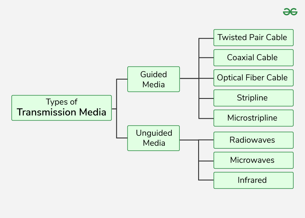
1. Guided Media
1. Twisted Pair Cable
It consists of 2 separately insulated conductor wires wound about each other. Generally, several such pairs are bundled together in a protective sheath. They are the most widely used Transmission Media. Twisted Pair is of two types:
- Unshielded Twisted Pair (UTP):UTP consists of two insulated copper wires twisted around one another. This type of cable has the ability to block interference and does not depend on a physical shield for this purpose. It is used for telephonic applications.

Advantages of Unshielded Twisted Pair
- Least expensive
- Easy to install
- High-speed capacity
Disadvantages of Unshielded Twisted Pair
- Lower capacity and performance in comparison to STP
- Short distance transmission due to attenuation
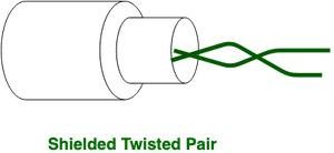
Shielded Twisted Pair (STP): Shielded Twisted Pair (STP) cable consists of a special jacket (a copper braid covering or a foil shield) to block external interference. It is used in fast-data-rate Ethernet and in voice and data channels of telephone lines.
Advantages of Shielded Twisted Pair
- Better performance at a higher data rate in comparison to UTP
- Eliminates crosstalk
- Comparatively faster
Disadvantages of Shielded Twisted Pair
- Comparatively difficult to install and manufacture
- More expensive
- Bulky
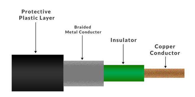
2. Coaxial Cable
Coaxial cable has an outer plastic covering containing an insulation layer made of PVC or Teflon and 2 parallel conductors each having a separate insulated protection cover. The coaxial cable transmits information in two modes: Baseband mode(dedicated cable bandwidth) and Broadband mode(cable bandwidth is split into separate ranges). Cable TVs and analog television networks widely use Coaxial cables.
Advantages of Coaxial Cable
- Coaxial cables has high bandwidth .
- It is easy to install.
- Coaxial cables are more reliable and durable.
- Less affected by noise or cross-talk or electromagnetic inference.
- Coaxial cables support multiple channels
Disadvantages of Coaxial Cable
- Coaxial cables are expensive.
- The coaxial cable must be grounded in order to prevent any crosstalk.
- As a Coaxial cable has multiple layers it is very bulky.
- There is a chance of breaking the coaxial cable and attaching a “t-joint” by hackers, this compromises the security of the data.
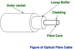
3. Optical Fiber Cable
Optical Fibre Cable uses the concept total internal reflection of light through a core made up of glass. The core is surrounded by a less dense glass or plastic covering called the coating. It is used for the transmission of large volumes of data. The cable can be unidirectional or bidirectional. The WDM (Wavelength Division Multiplexer) supports two modes, namely unidirectional and bidirectional mode.
Advantages of Optical Fibre Cable
- Increased capacity and bandwidth
- Lightweight
- Less signal attenuation
- Immunity to electromagnetic interference
- Resistance to corrosive materials
Disadvantages of Optical Fibre Cable
- Difficult to install and maintain
- High cost
Applications of Optical Fibre Cable
- Medical Purpose: Used in several types of medical instruments.
- Defence Purpose: Used in transmission of data in aerospace.
- For Communication: This is largely used in formation of internet cables.
- Industrial Purpose: Used for lighting purposes and safety measures in designing the interior and exterior of automobiles.
2. Unguided Media
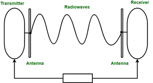
1. Radio Waves
Radio waves are easy to generate and can penetrate through buildings. The sending and receiving antennas need not be aligned. Frequency Range:3KHz – 1GHz. AM and FM radios and cordless phones use Radio waves for transmission.
Types of Radio Waves:
- Short Wave: AM Radio
- VHF (Very High Frequency): FM Radio/TV
- UHF (Ultra High Frequency): TV
Radio Wave Components:
- Transmitter: Responsible for encoding the signal.
- *Receiver: Responsible for decoding the signal.
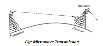
2. Microwaves
It is a line of sight transmission i.e. the sending and receiving antennas need to be properly aligned with each other. The distance covered by the signal is directly proportional to the height of the antenna. Frequency Range:1GHz – 300GHz. Micro waves are majorly used for mobile phone communication and television distribution.
Advantages:
- Cheaper than using cables
- Freedom from land acquisition
- Ease of communication in difficult terrains
- Communication over oceans
Disadvantages:
- Insecure communication.
- Out-of-phase signal.
- Susceptible to weather conditions.
- Bandwidth is limited.
- High cost of design, implementation, and maintenance.
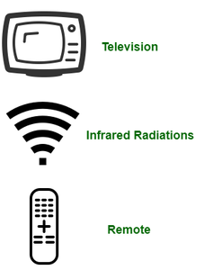
3. Infrared
Infrared waves are used for very short distance communication. They cannot penetrate through obstacles. This prevents interference between systems. Frequency Range:300GHz – 400THz. It is used in TV remotes, wireless mouse, keyboard, printer, etc.
Difference Between Radio Waves, Micro Waves, and Infrared Waves
| Basis | Radiowave | Microwave | Infrared wave |
|---|---|---|---|
| Direction | These are omni-directional in nature. | These are unidirectional in nature. | These are unidirectional in nature. |
| Penetration | At low frequency, they can penetrate through solid objects and walls but high frequency they bounce off the obstacle. | At low frequency, they can penetrate through solid objects and walls. at high frequency, they cannot penetrate. | They cannot penetrate through any solid object and walls. |
| Frequency range | Frequency range: 3 KHz to 1GHz. | Frequency range: 1 GHz to 300 GHz. | Frequency range: 300 GHz to 400 GHz. |
| Security | These offers poor security. | These offers medium security. | These offers high security. |
| Attenuation | Attenuation is high. | Attenuation is variable. | Attenuation is low. |
| Government License | Some frequencies in the radio-waves require government license to use these. | Some frequencies in the microwaves require government license to use these. | There is no need of government license to use these waves. |
| Usage Cost | Setup and usage Cost is moderate. | Setup and usage Cost is high. | Usage Cost is very less. |
| Communication | These are used in long distance communication. | These are used in long distance communication. | These are not used in long distance communication. |
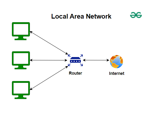
LAN : Local Area Network
A Local Area Network (LAN) is a network that interconnects devices within a limited geographic area—typically a home, office, or campus. LANs are designed for high-speed communication and resource sharing (like printers, files, and applications) among connected devices.
Key Characteristics:
- Limited Range: Covers a small physical area.
- High Data Transfer Rates: Offers fast data speeds, usually in the range of 100 Mbps to several Gbps.
- Low Latency: Minimal delay in data transmission.
- Ownership and Management: Typically owned, managed, and maintained by an individual or organization.
Wired LAN (also known as Ethernet)
https://www.geeksforgeeks.org/what-is-ethernet/
A Wired LAN uses physical cabling (such as Ethernet cables) to connect devices. This is the traditional method of establishing LAN connectivity.
Features:
- Physical Media: Uses copper cables (like Cat 5e, Cat 6) or fiber optics for high-speed data transmission.
- Reliability & Security: Physical connections tend to be more reliable and secure from external interference or unauthorized access.
- Stable Performance: Less prone to environmental factors such as radio interference, making it ideal for consistent, high-bandwidth applications.
Common Components:
- Switches & Routers: Devices that manage data traffic between connected devices.
- Network Interface Cards (NICs): Hardware installed in each device to interface with the wired network.
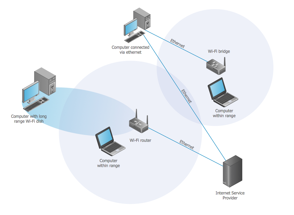
Wireless Lan (Wi-Fi or WLAN)
Overview:
A Wireless LAN uses radio waves instead of cables to connect devices. The most common example is Wi-Fi, which enables devices like laptops, smartphones, and tablets to access the network.
Features:
- Flexibility & Mobility: Devices can connect from different locations within the network’s range, offering greater mobility.
- Ease of Installation: No need to run cables through walls or ceilings; access points can be placed strategically.
- Potential Interference: Subject to interference from other wireless devices or physical obstacles, which may affect performance.
- Security Considerations: Requires robust encryption (such as WPA3) and proper configuration to prevent unauthorized access.
Common Components:
- Access Points (APs): Devices that broadcast and manage the wireless signal.
- Wireless Routers: Often combine the functionality of an AP with routing and security features.
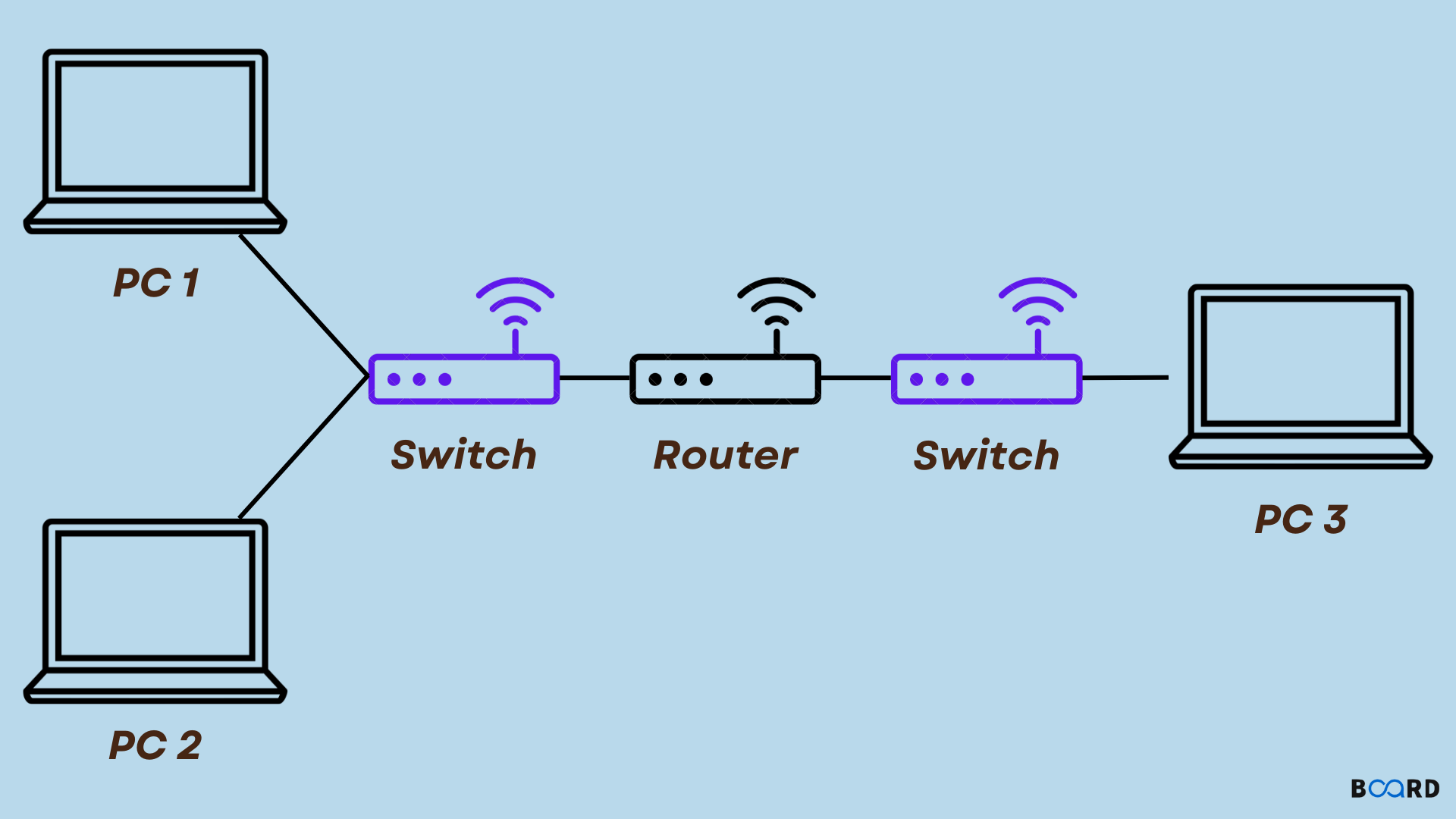
Connecting LANs
Overview:
Connecting LANs can refer to linking different segments or separate LANs together to form a larger network or to allow communication between them. This is important in larger organizations or multi-building campuses.
Methods & Components:
- Switches & Bridges: These devices help connect and segment LANs by forwarding data within the same network or between closely located segments.
- Routers: Used to interconnect separate LANs or connect a LAN to other networks (e.g., a WAN or the internet). Routers perform routing functions based on IP addresses.
- Gateways: Act as an entry point that can convert data between different network protocols or architectures.
- Wireless Repeaters & Mesh Systems: In a WLAN setup, these can extend the range or connect separate wireless networks.
Benefits:
- Scalability: Allows networks to grow without compromising performance.
- Resource Sharing: Facilitates the sharing of files, printers, and internet connections across multiple LAN segments.
- Enhanced Management: Segmented networks can be managed more effectively for security and performance.
Virtual LAN (VLAN)
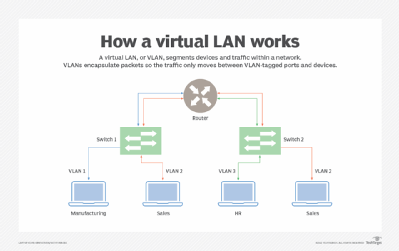
A Virtual LAN (VLAN) is a logical grouping of devices on one or more physical LANs that are segmented to create separate broadcast domains. Although the devices might be connected to the same physical network, VLANs allow network administrators to partition the network logically.
Key Characteristics:
- Logical Segmentation: Devices are grouped based on function, department, or project requirements regardless of their physical location.
- Improved Security: Sensitive data can be isolated within a VLAN, reducing the risk of unauthorized access.
- Reduced Broadcast Traffic: By limiting broadcast domains, VLANs help reduce network congestion and improve performance.
- Simplified Management: Changes to network structure (e.g., moving a device from one group to another) can be done via software configuration rather than physical re-cabling.
Implementation Techniques:
- Tagging (IEEE 802.1Q): Frames are tagged with a VLAN identifier so that switches can recognize which VLAN the frame belongs to.
- Trunk Ports: Special ports on switches that carry traffic for multiple VLANs, essential for connecting different VLAN segments across switches.
- Managed Switches: Required to configure and enforce VLAN settings, as they allow network segmentation based on VLAN IDs.
Multiplexing Techniques (Bandwidth Utilization)
Multiplexing is a technique that allows multiple signals or data streams to be combined and transmitted simultaneously over a single communication channel. This maximizes the use of the available bandwidth.
a. Frequency Division Multiplexing (FDM)
- Concept: Divides the available bandwidth of a communication channel into multiple non-overlapping frequency bands.
- Operation: Each signal is modulated with a different carrier frequency and occupies a distinct frequency slot.
- Applications: Radio and TV broadcasting, traditional telephone systems.
- Advantages/Disadvantages:
- Advantage: Continuous data transmission for each channel.
- Disadvantage: Requires guard bands between channels to prevent interference, which can reduce overall spectral efficiency.
b. Time Division Multiplexing (TDM)
- Concept: Divides the transmission time on a channel into sequential time slots, with each slot allocated to a different signal.
- Operation: Each channel transmits in rapid succession; the process repeats cyclically.
- Types:
- Synchronous TDM: Time slots are pre-assigned regardless of whether data is being sent.
- Statistical TDM: Time slots are dynamically allocated based on demand, which can improve efficiency.
- Applications: Digital telephony, ISDN, and some cellular systems.
c. Wavelength Division Multiplexing (WDM)
- Concept: Used in fiber-optic communications, WDM is analogous to FDM but with light wavelengths.
- Operation: Multiple optical carrier signals are transmitted on a single fiber by using different wavelengths (colors) of laser light.
- Applications: High-capacity telecommunications, internet backbone networks.
- Advantage: Can significantly increase the capacity of optical fiber without laying additional cables.
Spread Spectrum
Spread spectrum is a method used primarily in wireless communications to spread the transmitted signal over a wider bandwidth than the minimum required. This technique enhances security and resistance to interference.
Key Concepts
- Purpose:
- Interference Resistance: Makes the signal less susceptible to narrowband interference and jamming.
- Security: Difficult for eavesdroppers to intercept or jam due to the wide frequency range.
- Common Techniques:
- Direct Sequence Spread Spectrum (DSSS):
- Operation: The original data signal is multiplied by a pseudo-random noise code (also known as a spreading code), which spreads the signal over a broader frequency band.
- Example: Used in the IEEE 802.11b Wi-Fi standard.
- Frequency Hopping Spread Spectrum (FHSS):
- Operation: The carrier frequency rapidly changes or "hops" among many frequencies in a pseudo-random sequence, making it less predictable and more robust against interference.
- Example: Used in Bluetooth and some military communication systems.
- Direct Sequence Spread Spectrum (DSSS):
Spread spectrum techniques are critical for modern wireless communication standards because they improve both performance and security.