Module 2 -- Data Link Layer and Medium Access Sub Layer -- Computer Networks
Index
- Data Link Layer (Layer 2 of the OSI Model)
- Error Detection and Correction (with some error detection techniques)
- Flow Control
- 1. Stop-And-Wait ARQ
- 2. Go Back -N ARQ
- 3. Selective Repeat ARQ
- 4. Piggybacking
- Random Access And Multiple Access Protocols
- The ALOHA Protocol
- 1. Pure ALOHA
- 2. Slotted ALOHA
- 3. CSMA (Carrier Sense Multiple Access Protocol)
- CSMA/CD (Collision Detection)
- CSMA/CA (Collision Avoidance)
Data Link Layer (Layer 2 of the OSI Model)
https://www.youtube.com/watch?v=JRgmPco0KWI&list=PLxCzCOWd7aiGFBD2-2joCpWOLUrDLvVV_&index=22
The Data Link Layer (DLL) is the second layer in the OSI model and plays a vital role in ensuring reliable communication over a single link or hop in a network. It serves as an intermediary between the Physical Layer (which transmits raw bits) and the Network Layer (which handles end-to-end delivery across multiple networks). Here’s an in-depth look at its features and functionalities:
1. Core Functions of the Data Link Layer
a. Hop-to-Hop (Node-to-Node) Delivery
-
Definition:
The DLL is responsible for delivering data from one node (or hop) to the next within the same network segment. It does not take responsibility for the complete end-to-end delivery—that task falls to the Network Layer. -
Role:
Every time a packet moves from one router or network node to the next, the Data Link Layer handles the local delivery. Think of it as ensuring each segment of a train journey reaches its next station safely before the next segment takes over.
b. Flow Control
-
Purpose:
Flow control prevents a fast sender from overwhelming a slower receiver (or an intermediate node) by regulating the rate of data transmission. -
Techniques:
The DLL uses several protocols such as:-
Stop-and-Wait: The sender waits for an acknowledgment after sending each frame before transmitting the next one.
-
Go-Back-N: Multiple frames are sent, but if an error is detected, the sender goes back to the erroneous frame and resends it along with all subsequent frames.
-
Selective Repeat: Only the frames that are detected as erroneous are retransmitted, rather than all frames following the error.
-
-
Application:
This control is crucial at each hop to avoid buffer overflow in devices like routers or switches, ensuring smooth and reliable communication.
c. Error Control
-
Objective:
The DLL must ensure that the data arriving at the next node is free from errors. This is especially important over unreliable physical mediums where interference or noise may alter the data. -
Error Detection and Correction Mechanisms:
-
Error Detection:
Techniques such as Cyclic Redundancy Check (CRC) and parity bits are used to detect errors in the transmitted frames. -
Error Correction:
Once an error is detected, mechanisms like automatic repeat request (ARQ) protocols allow the sender to retransmit the faulty frame.
-
-
Efficiency:
By detecting errors at each hop rather than waiting until the final destination, the network can correct problems more quickly, which improves overall performance.
d. Access Control (Media Access Control)
-
Function:
Access control manages how multiple devices share a common transmission medium. It ensures that only one device transmits at a time to avoid collisions (simultaneous data transmissions that can corrupt the data). -
Methods:
Various protocols and techniques are employed, such as:-
CSMA/CD (Carrier Sense Multiple Access with Collision Detection): Used in Ethernet networks, where devices listen for a free channel before transmitting.
-
CSMA/CA (Carrier Sense Multiple Access with Collision Avoidance): Often used in wireless networks to reduce the chance of collisions.
-
Token Passing: In methods like token ring or token bus, a token is passed around the network, and only the device holding the token can transmit.
-
-
Result:
These protocols help manage the access to the shared medium, ensuring orderly communication and reducing data collisions.
e. Physical Addressing
-
Role:
Each device on a local network is assigned a unique physical address, often referred to as a MAC (Media Access Control) address. -
Usage:
The Data Link Layer uses these addresses to deliver frames within the same local network. Unlike IP addresses (used by the Network Layer), MAC addresses are typically fixed and specific to the hardware. -
Significance:
This addressing scheme ensures that data frames are delivered to the correct recipient within a local area network (LAN).
f. Framing
-
Concept:
Framing is the process of encapsulating network layer packets into frames before transmission. A frame is a structured package that contains:-
Header: Information such as source and destination MAC addresses.
-
Payload: The actual data coming from the Network Layer.
-
Trailer: Often includes error-checking data (e.g., CRC) to verify frame integrity.
-
-
Advantages:
By breaking data into manageable frames with identifiable start and end points, the DLL enhances data synchronization and error detection, ensuring that frames are transmitted and received accurately.
2. Interplay with Other OSI Layers
-
With the Physical Layer:
The DLL takes the binary stream from the Physical Layer and organizes it into frames. It also handles issues like signal synchronization and ensures that the physical transmission is interpreted correctly. -
With the Network Layer:
Once the frames are properly constructed and error-checked, the DLL passes the data up to the Network Layer, which takes care of the end-to-end delivery across different networks.
3. Summary
The Data Link Layer is essential for:
-
Ensuring Reliable Local Communication: By managing hop-to-hop delivery, it guarantees that data is successfully transferred from one node to the next.
-
Regulating Data Flow: Through flow control mechanisms, it prevents congestion and data loss.
-
Detecting and Correcting Errors: Its error control functions quickly identify and rectify transmission errors, enhancing overall network reliability.
-
Controlling Access: It manages how devices share a common transmission medium, avoiding collisions.
-
Addressing and Framing: It uses MAC addresses for device identification and encapsulates data into frames for structured transmission.
Error Detection and Correction (with some error detection techniques)
Error Detection vs. Error Correction
-
Error Detection:
These techniques identify that an error has occurred during transmission. They do not always tell you where the error is, but they signal that the received data is not identical to the sent data. -
Error Correction:
These techniques go a step further by not only detecting that an error has occurred but also pinpointing its location and automatically correcting it. This is critical in environments where retransmission is difficult or impossible.
Hamming Distance
What Is Hamming Distance?
-
Hamming Distance is a measure of how different two code words are. It is defined as the number of positions in which the corresponding bits differ.
-
Calculation:
-
Perform an EXCLUSIVE OR (XOR) between two binary strings.
-
Count the number of 1s in the result (each 1 represents a difference).
-
Examples
-
Example 1:
Code Words:0000and1111
XOR:0000 ⊕ 1111 = 1111- Hamming Distance: 4 (all four bits differ)
-
Example 2:
Code Words:0101and1000
XOR:0101 ⊕ 1000 = 1101- Hamming Distance: Count the 1s → 3 differences
Minimum Hamming Distance and Its Importance
-
Minimum Hamming Distance (d):
- Among all pairs of valid code words, the smallest Hamming distance is very important.
-
Error Detection Capability:
-
A code with a minimum Hamming distance of d can reliably detect up to (d – 1) bit errors.
-
Example:
- If d = 2 (as often seen with single bit parity), the system can detect single bit errors (2 – 1 = 1) but not all double bit errors.
-
-
Error Correction:
- To not only detect but also correct errors, a larger Hamming distance is needed. For example, a Hamming distance of 3 is required to correct a single bit error in more sophisticated coding schemes.
Why Hamming Distance Matters
-
Reliability of Communication:
- The higher the minimum Hamming distance, the more robust the error detection (and correction) capabilities of the code.
-
Trade-offs:
-
There is a balance between the number of redundant bits added and the level of error detection/correction desired.
-
Single Parity Checking is very economical in terms of extra bits, but its minimum Hamming distance is low (usually 2), meaning it can only detect single bit errors reliably.
-
2. Error Detection Techniques
A. Single-Bit Parity Check
https://www.youtube.com/watch?v=U09cNsiYpc8&list=PLxCzCOWd7aiGFBD2-2joCpWOLUrDLvVV_&index=29
What Is Parity?
-
Parity is a simple error detection method used to ensure that data is transmitted with a basic level of integrity.
-
In Single Bit Parity Checking, an extra bit (called the parity bit) is added to the data word to make the total number of 1s either even or odd.
Types of Parity Bits
A parity bit is a bit appended to a data of binary bits to ensure that the total number of 1’s in the data is even or odd. Parity bits are used for error detection. There are two types of parity bits:
- Even Parity Bit: In the case of even parity, for a given set of bits, the number of 1’s are counted. If that count is odd, the parity bit value is set to 1, making the total count of occurrences of 1’s an even number. If the total number of 1’s in a given set of bits is already even, the parity bit’s value is 0.
- Odd Parity Bit: In the case of odd parity, for a given set of bits, the number of 1’s are counted. If that count is even, the parity bit value is set to 1, making the total count of occurrences of 1’s an odd number. If the total number of 1’s in a given set of bits is already odd, the parity bit’s value is 0.
The m+1 Rule
-
If your data word has m bits, you append 1 extra bit (thus, m+1 bits in total).
-
This extra bit is chosen so that the total number of 1s in the code word satisfies the desired parity:
-
Even Parity: The total number of 1s should be even.
-
Odd Parity: The total number of 1s should be odd.
-
How It Works (Using Even Parity as an Example)
-
Example 1:
Data:1010
Count the number of 1s: 2 (which is already even).-
Parity Bit:
0is added (because adding 0 keeps the count even). -
Code Word:
10100
-
-
Example 2:
Data:1110
Count the number of 1s: 3 (odd).-
Parity Bit:
1is added (because 3 + 1 = 4, an even number). -
Code Word:
11101
-
Error Detection Capability
-
Single Bit Errors:
-
If one bit in the transmitted code word is flipped (e.g., due to noise), the parity check at the receiver will fail.
-
Detection: The receiver recomputes the parity; if it does not match the expected (even or odd), an error is flagged.
-
-
Limitations:
-
Double Bit Errors: If two bits flip, the parity might still be correct (for even parity, 2 flips will still yield an even count).
-
General Rule:
-
Parity checking reliably detects any error that changes an odd number of bits.
-
It does not detect errors that flip an even number of bits.
-
-
Cost and Simplicity
-
Least Expensive Method:
-
Only one extra bit is transmitted, minimizing redundancy and bandwidth overhead.
-
It’s simple and low-cost, which makes it attractive for applications where minimal error detection is acceptable (e.g., audio streaming where minor errors might be tolerable).
-
-
Mechanism:
A parity bit is added to the data. For even parity, the bit is chosen so that the total number of 1s in the data (including the parity bit) is even. For odd parity, it ensures an odd count. -
Error Detection:
-
Detection: Any single-bit error will change the overall parity, alerting the receiver to the error.
-
Limitation:
-
It can only reliably detect an odd number of bit errors.
-
It cannot detect errors if two bits flip (because the parity might still be correct).
-
-
-
Hamming Distance Consideration:
The code generated by adding a single parity bit has a minimum Hamming distance of 2, meaning it can detect any single-bit error but lacks the redundancy needed for correction.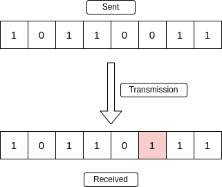
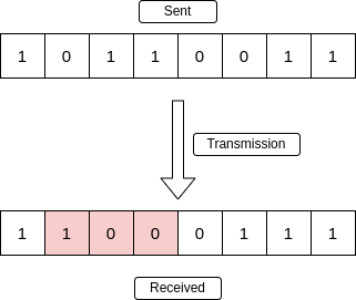
This is a single bit error. It happens when the bits in the received data is not the same as the sent data.
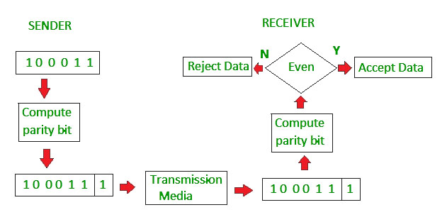
This picture depicts even parity checking. The receiver only accepts the data if the computed parity bit is even.
Some more types of errors (relevant in CRC):
Multiple Bit Error
A multiple-bit error is an error type that arises when more than one bit in a data transmission is affected. Although multiple-bit errors are relatively rare when compared to single-bit errors, they can still occur, particularly in high-noise or high-interference digital environments.
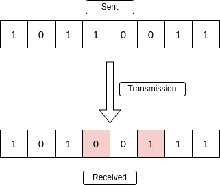
Burst Error
When several consecutive bits are flipped mistakenly in digital transmission, it creates a burst error. This error causes a sequence of consecutive incorrect values.
B. Cyclic Redundancy Check (CRC) and Modulo-2 Division
https://www.youtube.com/watch?v=5Q-Yv6_0Qcw&list=PLxCzCOWd7aiGFBD2-2joCpWOLUrDLvVV_&index=30
https://www.geeksforgeeks.org/modulo-2-binary-division/
CRC or Cyclic Redundancy Check is a method of detecting accidental changes/errors in the communication channel.
CRC uses Generator Polynomial which is available on both sender and receiver side. An example generator polynomial is of the form like
n : Number of bits in data to be sent
    from sender side.
k : Number of bits in the key obtained
    from generator polynomial.
1. Why CRC?
-
Powerful Error Detection:
CRC is capable of detecting:-
Single-bit errors, double-bit errors, and all odd-numbered bit errors.
-
Burst errors (errors occurring in contiguous sequences) of a length up to the degree of the polynomial used.
-
-
Efficiency:
CRC adds a small number of redundant bits relative to the original message (often described using the “m + r” rule, where m is the number of message bits and r is the number of redundant bits).
2. CRC Process Overview
a. Representing Data and Divisor
-
Data (Dividend):
The original message (or dividend) can be given in binary or polynomial form. -
Divisor (Generator Polynomial):
The divisor is given as a polynomial (e.g.,). - Conversion to Binary:
Each term’s coefficient is extracted. For instance,becomes the binary number 11001 (since the coefficients are for , for , for , for , and for ).
- Conversion to Binary:
b. Determining the Number of Redundant Bits (r)
What is Redundant Bits?
Redundant bits are extra binary bits that are generated and added to the information-carrying bits of data transfer to ensure that no bits were lost during the data transfer. The number of redundant bits can be calculated using the following formula:
where m is the number of bits in input data, and r is the number of redundant bits.
Suppose the number of data bits is 7, then the number of redundant bits can be calculated using: =
-
Rule:
-
If the divisor is given as a polynomial with maximum degree
, then append r zeros to the data. -
If the divisor is provided in binary and has
bits, then append n – 1 zeros.
-
-
Example:
For a divisor represented as 11001 (degree 4), you append 4 zeros to the original data.
c. Binary Division Using XOR
-
Division Process:
-
The augmented data (original message with appended zeros) is divided by the divisor using binary division, where subtraction is replaced by the XOR operation.
-
XOR Operation:
-
Same bits (1 ⊕ 1 or 0 ⊕ 0 ) yield 0.
-
Different bits (1 ⊕ 0 or 0 ⊕ 1) yield 1.
-
-
-
Step-by-Step:
-
Align the Divisor: Start with the leftmost 1 of the dividend.
-
Perform XOR: Apply XOR between the bits of the divisor and the corresponding bits of the dividend.
-
Shift and Repeat: Bring down the next bit from the augmented data and continue the process until the entire dividend has been processed.
-
Remainder Extraction: The result of this division is a remainder of r bits.
-
d. Creating the Codeword
-
Codeword Formation:
Replace the appended zeros with the remainder bits. The new sequence, which consists of the original data followed by the remainder, forms the final codeword. -
Transmission:
This codeword is transmitted to the receiver.
3. Error Detection at the Receiver
-
Receiver’s Check:
Upon receiving the codeword, the receiver performs the same binary division using the identical divisor. -
Outcome:
-
If the resulting remainder is zero, the data is considered error‑free.
-
If the remainder is non-zero, an error has been detected.
-
-
Reliability:
Because of the properties of the chosen polynomial, CRC can detect a wide range of errors:-
It detects any error that changes an odd number of bits.
-
It can detect burst errors up to a length equal to the degree of the generator polynomial.
-
4. Efficiency and Practical Considerations
-
Efficiency Calculation:
For example, if the original data is 10 bits (m = 10) and you append 4 bits (r = 4) because of a degree-4 polynomial, the total transmitted bits become 14.-
Channel Utilization:
-
-
Real-World Use:
Due to its strong error detection capability and relatively low overhead, CRC is used in many communication protocols and storage devices.
How CRC is used
Sender Side (Generation of Encoded Data from Data and Generator Polynomial (or Key)):
- The binary data is first augmented by adding k-1 zeros in the end of the data
- Use modulo-2 binary division to divide binary data by the key and store remainder of division.
- Append the remainder at the end of the data to form the encoded data and send the same
Receiver Side (Check if there are errors introduced in transmission)
Perform modulo-2 division again and if the remainder is 0, then there are no errors.
In this article we will focus only on finding the remainder i.e. check word and the code word.
Modulo 2 Division:
The process of modulo-2 binary division is the same as the familiar division process we use for decimal numbers. Just that instead of subtraction, we use XOR here.
- In each step, a copy of the divisor (or data) is XORed with the k bits of the dividend (or key).
- The result of the XOR operation (remainder) is (n-1) bits, which is used for the next step after 1 extra bit is pulled down to make it n bits long.
- When there are no bits left to pull down, we have a result. The (n-1)-bit remainder which is appended at the sender side.
Worked out example
1. No error
Data word to be sent - 100100
Key - 1101 Or generator polynomial
Sender Side:

Note what we added
So we have added 3 zeroes at the end of the original data word.
Therefore, the remainder is 001 and hence the encoded
data sent is 100100001.
Receiver Side:
Code word received at the receiver side 100100001.
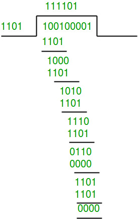
Therefore, the remainder is all zeros. Hence, the
data received has no error.
2. Error in transmission
Data word to be sent - 100100
Key - 1101
Sender Side:
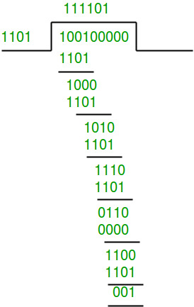
Therefore, the remainder is 001 and hence the
code word sent is 100100001.
Receiver Side
Let there be an error in transmission media
Code word received at the receiver side - 100000001
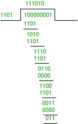
Since the remainder is not all zeroes, the error
is detected at the receiver side.
3. Error Correction Techniques
C. Hamming Code
https://www.youtube.com/watch?v=WdmGSWrcMvM
-
Mechanism:
Hamming Code involves adding multiple parity bits to the original data at positions that are powers of 2 (e.g., positions 1, 2, 4, 8, …). These bits are calculated so that each covers a unique combination of bits in the data. -
Error Correction Process:
-
Detection:
-
When data is received, the parity bits are re-calculated and compared with the received parity bits.
-
The pattern of discrepancies (if any) forms a binary number that directly points to the position of the erroneous bit.
-
-
Correction:
- Once the error position is identified, that bit can be flipped to correct the error.
-
-
Capabilities:
-
Hamming Code can detect and correct single-bit errors.
-
It can also detect (but not correct) double-bit errors because the erroneous pattern will not correspond to a single bit flip.
-
-
Hamming Distance:
The design of Hamming Code typically results in a minimum Hamming distance of 3. This allows it to correct one error (since) and detect two errors.
Algorithm of Hamming Code
https://www.youtube.com/watch?v=1A_NcXxdoCc (Error detection)
https://www.youtube.com/watch?v=wbH2VxzmoZk (Error correction)
Hamming Code is simply the use of extra parity bits to allow the identification of an error.
Step 1: Write the bit positions starting from 1 in binary form (1, 10, 11, 100, etc.).
Step 2: All the bit positions that are a power of 2 are marked as parity bits (1, 2, 4, 8, etc.).
Step 3: All the other bit positions are marked as data bits.
Step 4: Each data bit is included in a unique set of parity bits, as determined its bit position in binary form:
- a. Parity bit 1 covers all the bits positions whose binary representation includes a 1 in the least significant position (1, 3, 5, 7, 9, 11, etc.).
- b. Parity bit 2 covers all the bits positions whose binary representation includes a 1 in the second position from the least significant bit (2, 3, 6, 7, 10, 11, etc.).
- c. Parity bit 4 covers all the bits positions whose binary representation includes a 1 in the third position from the least significant bit (4–7, 12–15, 20–23, etc.).
- d. Parity bit 8 covers all the bits positions whose binary representation includes a 1 in the fourth position from the least significant bit bits (8–15, 24–31, 40–47, etc.).
- e. In general, each parity bit covers all bits where the bitwise AND of the parity position and the bit position is non-zero.
Step 5: Since we check for even parity set a parity bit to 1 if the total number of ones in the positions it checks is odd. Set a parity bit to 0 if the total number of ones in the positions it checks is even.
Summary
-
Single-Bit Parity Check:
- Usage: Simple error detection.
- Mechanism: Adds one parity bit to ensure an even or odd number of 1s.
- Limitation: Can only detect an odd number of errors; minimum Hamming distance = 2.
-
CRC:
- Usage: Robust error detection in data transmission and storage.
- Mechanism: Divides data by a predefined polynomial and appends the remainder.
- Limitation: Detects errors but does not correct them.
-
Hamming Code:
- Usage: Error correction where retransmission is not feasible.
- Mechanism: Inserts multiple parity bits at positions that are powers of 2, using their pattern to detect and correct single-bit errors.
- Capability: Corrects single-bit errors and detects double-bit errors; minimum Hamming distance = 3.
D. Block Coding
Block coding is a technique used in digital communications and error control where data is divided into fixed-size blocks (or words), and each block is encoded by adding extra bits (redundancy) to form a codeword. These extra bits enable the detection and, in many cases, the correction of errors that might occur during transmission. Here’s a detailed explanation:
1. Basic Concept
-
Fixed-Size Blocks:
In block coding, the original data is split into blocks of a fixed length, typically denoted asbits (message bits). -
Codeword Formation:
Each-bit block is then transformed into an -bit codeword by appending redundant bits. This process is done using an encoding algorithm. -
Code Rate:
The ratiois called the code rate. It reflects the efficiency of the coding scheme—higher rates mean less redundancy but may offer weaker error control.
2. Types of Block Codes
- Linear Block Codes:
These codes are defined over a finite field (often binary, GF(2)). They have the property that any linear combination of codewords is also a valid codeword. Examples include:- Hamming Codes: Provide single-bit error correction and double-bit error detection.
- Reed-Solomon Codes: Used widely in storage and digital broadcasting for correcting burst errors.
- Nonlinear Block Codes:
In these codes, the set of valid codewords does not necessarily form a linear subspace. They can sometimes achieve better error detection or correction performance at the cost of increased complexity.
3. Encoding and Decoding
-
Encoding Process:
An encoder takes a block of kk message bits and uses a predetermined rule (often represented by a generator matrix in linear block codes) to produce an n-bit codeword.- Example: For a Hamming code, the encoding matrix ensures that every codeword satisfies specific parity-check conditions.
-
Decoding Process:
When a codeword is received, the decoder checks for errors using redundant bits. In linear codes, this is often done using a parity-check matrix:- The received word is multiplied by the parity-check matrix.
- If the result (called the syndrome) is all zeros, no error is detected.
- A nonzero syndrome indicates the presence and sometimes the location of errors, allowing for error correction.
4. Error Detection and Correction
-
Error Detection:
Redundant bits help identify that an error has occurred. The system checks whether the codeword satisfies specific parity conditions. -
Error Correction:
Some block codes are designed not only to detect errors but also to pinpoint and correct them. The correction capability is related to the minimum Hamming distance (d) between valid codewords:- A minimum Hamming distance dd means the code can detect up to d−1d-1 errors.
- For correction, if d≥2t+1d \geq 2t+1, then the code can correct tt errors.
5. Advantages and Trade-offs
-
Reliability:
By introducing redundancy, block codes significantly improve the reliability of data transmission over noisy channels. -
Complexity vs. Overhead:
- Higher Redundancy: Offers better error detection and correction but reduces the effective data rate (lower code rate).
- Lower Redundancy: Increases efficiency but may not correct as many errors.
-
Application Specific:
The choice of block code depends on the application’s requirements—whether it needs to prioritize high throughput or robust error correction.
6. Real-World Applications
-
Digital Communications:
Block coding is used in wireless networks, satellite communications, and digital television to maintain data integrity. -
Storage Devices:
Hard drives, CDs, and DVDs use block codes (like Reed-Solomon) to correct errors due to scratches or defects. -
Data Transmission Standards:
Many modern communication standards (e.g., LTE, Wi-Fi) incorporate block coding techniques to improve performance in the presence of interference.
Flow Control
Flow Control Overview
-
Purpose:
Flow control prevents a sender from overwhelming a receiver by managing the pace of data transmission. -
Key Protocols:
- Stop-and-Wait ARQ: A simple, but less efficient method.
- Sliding Window Protocols: Include Go-Back-N ARQ and Selective Repeat ARQ, which improve throughput by allowing multiple frames in transit.
Some Flow control protocols :
1. Stop-And-Wait ARQ
https://www.geeksforgeeks.org/stop-and-wait-arq/
The Stop-and-Wait ARQ (Automatic Repeat Request) protocol is one of the simplest error control protocols used in data link layer communications. Its primary goal is to ensure that each frame is received correctly before the next one is transmitted. Here’s an in-depth look at how it works:
1. Operational Overview
Step-by-Step Process
-
Transmission of a Frame:
The sender transmits one data frame. -
Waiting for Acknowledgment (ACK):
After sending the frame, the sender stops and waits for an acknowledgment from the receiver. -
Acknowledgment Reception:
- If ACK is received within a set time: The sender concludes that the frame was correctly received and then transmits the next frame.
- If ACK is not received (due to an error or loss): The sender assumes that the frame was lost or corrupted and retransmits the same frame.
-
Error Handling:
The receiver checks the frame (often using error detection methods like parity bits or CRC) and sends an ACK if the frame is error-free, or a negative acknowledgment (NACK) if an error is detected (depending on the implementation).
2. Key Characteristics
Simplicity
- Ease of Implementation:
The protocol is straightforward because it deals with one frame at a time.
Reliability
- Error Correction through Retransmission:
If any frame is lost or arrives with errors, the protocol automatically triggers a retransmission, ensuring reliability.
Flow Control
- One-Frame-at-a-Time:
By sending only one frame and waiting for its ACK, the protocol naturally limits the data flow, preventing the receiver from being overwhelmed.
3. Throughput Considerations
Efficiency Formula
Throughput efficiency (the fraction of time used for transmitting useful data) is approximated by:
-
: Time required to transmit the frame. -
: One-way propagation delay. -
: Accounts for the round-trip time (sending the frame and waiting for the ACK).
Implication of High Latency
-
On links with high propagation delays (such as satellite or long-distance networks), the waiting time for an ACK becomes significant compared to the transmission time.
-
This leads to low throughput efficiency because the sender spends a lot of time waiting, rather than transmitting new frames.
4. Advantages and Disadvantages
Advantages
-
Simplicity:
Very easy to implement and understand. -
Low Buffer Requirements:
Since only one frame is in transit at any time, the memory and processing requirements are minimal.
Disadvantages
-
Low Efficiency on High-Latency Links:
The sender remains idle during the waiting period, significantly reducing throughput. -
Inefficiency in High-Bandwidth Networks:
As bandwidth increases (i.e., decreases relative to ), the idle waiting time becomes more pronounced. -
Not Scalable:
This protocol does not perform well when the communication channel has high delay-bandwidth products.
Characteristics of Stop and Wait ARQ
- Used in Connection-oriented communication.
- It offers error and flow control.
- It is used in Data Link and Transport Layers
- Stop and Wait for ARQ mainly implements the Sliding Window Protocol concept with Window Size 1
- It uses a link between sender and receiver as a half-duplex link
- Throughput = 1 Data packet/frame per RTT
- If the bandwidth*Delay product is very high, then they stop and wait for protocol if it is not so useful. The sender has to keep waiting for acknowledgments before sending the processed next packet.
- It is an example of “Closed Loop OR connection-oriented “ protocols
- It is a special category of SWP where its window size is 1
- Irrespective of the number of packets sender is having stop and wait for protocol requires only 2 sequence numbers 0 and 1
Useful Terms in Stop and Wait Protocol
- Propagation Delay: Amount of time taken by a packet to make a physical journey from one router to another router.
Propagation Delay = (Distance between routers) / (Velocity of propagation)
- RoundTripTime (RTT) = Amount of time taken by a packet to reach the receiver + Time taken by the Acknowledgement to reach the sender
- TimeOut (TO) = 2* RTT
- Time To Live (TTL) = 2* TimeOut. (Maximum TTL is 255 seconds)
Simple Stop and Wait
At Sender
- Rule 1: Send one data packet at a time.
- Rule 2: Send the next packet only after receiving acknowledgment for the previous.
At Receiver
- Rule 1: Send acknowledgement after receiving and consuming a data packet.
- Rule 2: After consuming packet acknowledgement need to be sent (Flow Control)
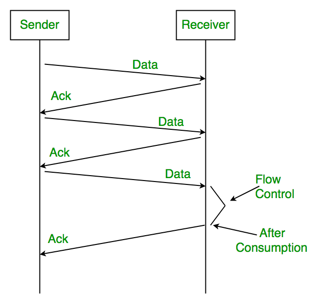
(After consumption) indicates that the packet sent to the receiver has been received and used successfully so the receiver sends (Ack) or acknowledgement to the sender, so that the sender can send the next packet.
5. Practical Example
Imagine a scenario where:
- Frame Transmission Time,
: 5 ms - One-Way Propagation Delay,
: 20 ms
The efficiency would be calculated as:
This means only about 11.1% of the total communication time is used for actual data transmission, with the rest spent waiting for acknowledgments.
Useful Terms in Stop and Wait Protocol
- Propagation Delay: Amount of time taken by a packet to make a physical journey from one router to another router.
Propagation Delay = (Distance between routers) / (Velocity of propagation)
- RoundTripTime (RTT) = Amount of time taken by a packet to reach the receiver + Time taken by the Acknowledgement to reach the sender
- TimeOut (TO) = 2* RTT
- Time To Live (TTL) = 2* TimeOut. (Maximum TTL is 255 seconds)
Problems Associated with Stop and Wait
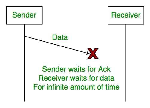
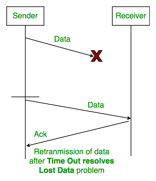
1. Lost Data
Assume the sender transmits the data packet and it is lost. The receiver has been waiting for the data for a long time. Because the data is not received by the receiver, it does not transmit an acknowledgment. The sender does not receive an acknowledgment, it will not send the next packet. This problem is caused by a loss of data.
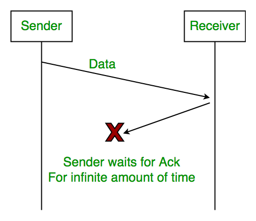
2. Lost Acknowledgement
Assume the sender sends the data, which is also received by the receiver. The receiver sends an acknowledgment after receiving the packet. In this situation, the acknowledgement is lost in the network. The sender does not send the next data packet because it does not receive acknowledgement, under the stop and wait protocol, the next packet cannot be transmitted until the preceding packet’s acknowledgment is received.
3. Delayed Acknowledgement/Data
Assume the sender sends the data, which is also received by the receiver. The receiver then transmits the acknowledgment, which is received after the sender’s timeout period. After a timeout on the sender side, a long-delayed acknowledgement might be wrongly considered as acknowledgement of some other recent packet.
Stop and Wait for ARQ (Automatic Repeat Request) (Solutions to the above problems)
The above 3 problems are resolved by Stop and Wait for ARQ (Automatic Repeat Request) that does both error control and flow control.
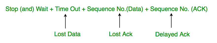
1. Time Out
Timeout refers to the duration for which the sender waits for an acknowledgment (ACK) from the receiver after transmitting a data packet. If the sender does not receive an ACK within this timeout period, it assumes that the frame was lost or corrupted and retransmits the frame.
2. Sequence Number (Data)
In Stop-and-Wait ARQ, the sender assigns sequence numbers to each data frame it sends. This allows the receiver to identify and acknowledge each frame individually, ensuring reliable delivery of data packets. After sending a frame, the sender waits for an acknowledgment before sending the next frame.
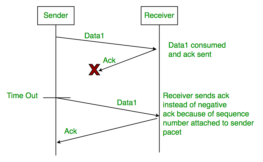
3. Sequence Number(Acknowledgement)
Similarly, sequence numbers are also used in acknowledgments (ACKs) sent by the receiver to acknowledge received data frames. When the receiver successfully receives a data frame, it sends an ACK back to the sender, indicating the sequence number of the next expected frame. The sender uses this ACK to determine whether the transmission was successful and whether it can proceed to send the next frame.
2. Go Back -N ARQ
https://www.youtube.com/watch?v=YIX1NfaUpsU&list=PLxCzCOWd7aiGFBD2-2joCpWOLUrDLvVV_&index=24
https://www.geeksforgeeks.org/sliding-window-protocol-set-2-receiver-side/
Go-Back-N ARQ is a sliding window protocol used for error control in data link layer communications. It allows the sender to transmit multiple frames before needing an acknowledgment (ACK) for the first frame, thereby improving throughput compared to the Stop-and-Wait protocol.
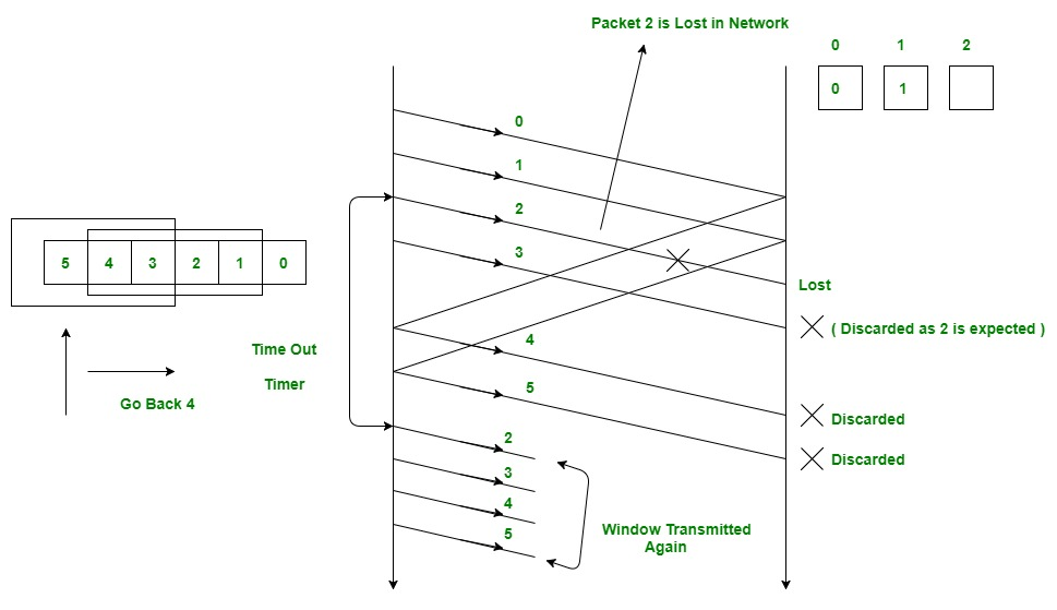
In this picture we see that in a single N window 4 packets are sent, namely, 0, 1, 2, 3.
We see that packet 2 is lost in the network so it doesn't reach the receiver.
When packet 3 reaches the receiver it's discarded since the receiver still expects packet 2.
Packets 0 and 1 are successfully received by the receiver which then sends Ack packets as packets 4 and 5 back to the sender.
In the next window the lost packet 2 along with the discarded packet 3 is transmitted again along with packets 4 and 5.
Note that this window is re-transmitted again only after sender receives Ack for the first frame/packet which is how Go Back -N ARQ works.
1. Operational Overview
Sliding Window Concept
-
Window Size:
The sender is allowed to send a fixed number of frames (defined by the window size) before it must stop and wait for an acknowledgment. For example, if the window size is NNN, the sender can transmit frames 1 through NNN consecutively. -
Continuous Transmission:
Once the sender transmits these frames, it continues sending new frames as long as the number of unacknowledged frames does not exceed the window size.
Handling Errors
-
Error Detection:
If an error is detected (typically via a checksum or CRC) in one of the transmitted frames, the receiver discards that frame along with all subsequent frames in the current window. -
Acknowledgment:
The receiver sends a cumulative acknowledgment indicating the highest sequence number of the frame received in order.- For example, if frames 1, 2, and 3 are received correctly but frame 4 is erroneous, the receiver will send an ACK for frame 3.
-
Retransmission:
Upon detecting a missing ACK (or receiving a duplicate ACK), the sender “goes back” to the erroneous frame and retransmits that frame along with all the following frames in the window, even if some were received correctly earlier.
2. Detailed Mechanism
Step-by-Step Process
-
Transmission:
The sender transmits a set of frames defined by the window size. Frames are numbered sequentially. -
Reception & Acknowledgment:
The receiver checks each frame. It accepts frames in order and sends back a cumulative acknowledgment for the last correctly received frame in order. -
Error Occurrence:
If a frame is found to be in error, the receiver discards it and any subsequent frames because they cannot be accepted out of order. -
Go-Back-N Action:
The sender, upon noticing that the expected acknowledgment has not advanced (or detecting a duplicate ACK), retransmits the erroneous frame and every subsequent frame in the window.
Example Scenario
-
Window Size = 4:
The sender transmits frames 1, 2, 3, and 4. -
Error in Frame 3:
The receiver accepts frames 1 and 2, but detects an error in frame 3. Even if frame 4 arrives correctly, the receiver ignores it. -
ACK Sent:
The receiver sends an ACK for frame 2 (the last in-sequence frame). -
Retransmission:
The sender, upon receiving the duplicate ACK for frame 2, retransmits frame 3 and then frame 4.
3. Advantages and Disadvantages
Advantages
-
Improved Throughput:
By allowing multiple frames to be in transit simultaneously, Go-Back-N increases the utilization of the communication channel, especially in environments with high propagation delays. -
Simple Implementation of Sliding Window:
The protocol is relatively straightforward to implement compared to more complex selective retransmission schemes.
Disadvantages
-
Inefficient Retransmission:
In the event of an error, not only is the erroneous frame retransmitted but also all frames that followed it, even if they were received correctly. This can lead to unnecessary retransmissions, especially if the error rate is high. -
Buffer Requirements:
Both sender and receiver must maintain buffers to store frames until they are acknowledged.
4. Throughput Consideration
-
Efficiency Impact:
Throughput is increased relative to Stop-and-Wait by having a window of frames in transit. However, efficiency can degrade if errors are frequent, as the retransmission of multiple frames wastes bandwidth. -
Window Size Trade-off:
A larger window size can increase throughput, but it also increases the potential for more data being retransmitted if an error occurs.
5. When to Use Go-Back-N ARQ
-
Reliable Communication Channels:
It is best suited for environments where errors are infrequent, so that the cost of retransmitting multiple frames is minimal. -
High-Latency Networks:
In networks with significant propagation delays, the ability to send several frames before needing an ACK helps to keep the channel busy and improves overall throughput.
3. Selective Repeat ARQ
https://www.youtube.com/watch?v=08y_Vrs1vHo&list=PLxCzCOWd7aiGFBD2-2joCpWOLUrDLvVV_&index=25
https://www.geeksforgeeks.org/sliding-window-protocol-set-3-selective-repeat/
Selective Repeat ARQ is an advanced error control protocol within the sliding window family. Unlike Go-Back-N, which retransmits all frames following an error, Selective Repeat ARQ retransmits only the individual frames that were received with errors. This selective retransmission can significantly improve throughput in environments where errors occur infrequently.
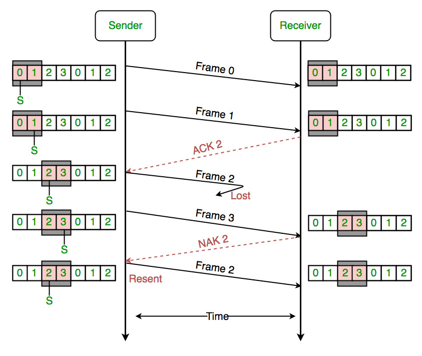
In this picture we see that that each frame contains two packets.
Frame 0 is sent first, starting with packet 0 to the receiver, followed by packet 1.
On receiving Frame 1 the receiver sends ACK to the sender that the frame has been received has been successfully received in the correct order.
Now frame 2 is sent from the sender but gets lost in the network.
But frame 3 is received successfully by the receiver, however since it didn't receive the preceding frame, it sends a NAK 2 or "Not acknowledged" to sender indicating that the frame 2 was not received by the receiver.
In the third section we see that the sender resends frame 2 along with a new frame lined up for sending as well after frame 2.
This way Selective repeat only resends the frames that are not received, thus saving time, computational and network resources.
1. Operational Overview
Sliding Window Concept
-
Window Size:
The sender is allowed to transmit multiple frames up to a defined window size before needing to wait for acknowledgments (ACKs). -
Independent Frame Tracking:
Both sender and receiver maintain separate buffers:-
Sender Buffer: Holds frames that have been transmitted but not yet acknowledged.
-
Receiver Buffer: Stores received frames that may arrive out-of-order until missing frames are received.
-
Independent Acknowledgments
-
ACK for Each Frame:
Unlike cumulative ACKs used in Go-Back-N, the receiver in Selective Repeat ARQ sends individual acknowledgments for each correctly received frame. -
Handling Out-of-Order Frames:
The receiver can accept frames that arrive out of order and hold them temporarily until the missing frames are received, ensuring that data is delivered in the correct sequence.
2. Step-by-Step Process
-
Transmission:
-
The sender transmits a sequence of frames within its window.
-
Each frame is assigned a sequence number to uniquely identify it.
-
-
Reception & Buffering:
-
The receiver checks each incoming frame for errors.
-
If a frame is received correctly, an individual ACK is sent back for that frame.
-
Out-of-order frames are stored in the receiver’s buffer until all preceding frames are correctly received.
-
-
Error Detection:
- If the receiver detects an error in a frame (via CRC or other error-checking mechanisms), that frame is not acknowledged.
-
Selective Retransmission:
-
The sender monitors ACKs. If an ACK for a specific frame is not received within a timeout period, only that particular frame is retransmitted.
-
This process continues until all frames are correctly acknowledged.
-
-
Reordering at the Receiver:
- Once the missing frames are received, the receiver reassembles the sequence in the correct order and delivers it to the higher layers.
3. Advantages and Disadvantages
Advantages
-
Efficient Use of Bandwidth:
By retransmitting only the erroneous frames, Selective Repeat minimizes unnecessary retransmissions, which is particularly beneficial in channels with sporadic errors. -
Better Throughput:
With fewer retransmissions compared to Go-Back-N, overall throughput is improved, especially in networks where errors are infrequent. -
Flexibility with Out-of-Order Delivery:
The receiver's ability to accept and buffer out-of-order frames allows for a more efficient and flexible handling of data.
Disadvantages
-
Increased Complexity:
-
Buffer Management: Both sender and receiver need to maintain buffers to store multiple frames.
-
Tracking and Reordering: The receiver must correctly reorder out-of-order frames, and the sender must track individual ACKs.
-
-
Implementation Overhead:
The protocol requires more sophisticated control logic compared to Stop-and-Wait or Go-Back-N, which can complicate the design and implementation of the communication system.
4. Throughput Consideration
-
Efficiency Gain:
In environments with low to moderate error rates, the efficiency gain from retransmitting only specific frames rather than entire windows can be substantial. -
Window Size Trade-off:
A properly chosen window size maximizes throughput while keeping the complexity of buffering and management within acceptable limits.
5. Example Scenario
Consider a sender with a window size of 4 transmitting frames numbered 1 to 4:
-
Normal Operation:
If frames 1, 2, and 4 are received correctly, but frame 3 is lost or corrupted, the receiver sends individual ACKs for 1, 2, and 4. -
Selective Retransmission:
The sender, noticing the missing ACK for frame 3, retransmits only frame 3. -
Reordering:
The receiver then places frame 3 in its proper sequence within the buffer and, once complete, delivers frames 1 through 4 in order.
4. Piggybacking
https://www.geeksforgeeks.org/piggybacking-in-computer-networks/
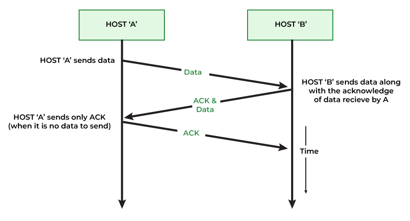
Piggybacking is an optimization technique used in two-way communication protocols at the data link layer. It involves combining (or "piggybacking") an acknowledgment (ACK) with outgoing data instead of sending the acknowledgment as a separate frame.
1. Concept and Purpose
-
Definition:
Piggybacking refers to the process where a node delays sending a standalone acknowledgment frame, waiting instead to send the ACK along with a data frame that is heading in the opposite direction. This effectively reduces the number of frames transmitted over the network. -
Purpose:
The main goals of piggybacking are to:-
Reduce Overhead: By combining ACKs with outgoing data, fewer frames are sent, leading to better utilization of the communication channel.
-
Improve Efficiency: Especially in bidirectional communication, piggybacking can significantly reduce protocol overhead, lowering the overall number of transmissions and associated delays.
-
2. How Piggybacking Works
Step-by-Step Process:
-
Receiving Data:
-
A sender transmits a data frame to a receiver.
-
The receiver processes the frame and prepares an acknowledgment.
-
-
Delaying the ACK:
-
Instead of immediately sending a separate ACK frame, the receiver waits for a brief period.
-
This waiting period allows the receiver to determine if it has data to send back to the original sender.
-
-
Combining Data and ACK:
-
If the receiver has data ready to transmit, it attaches (piggybacks) the ACK information within the header of the outgoing data frame.
-
The piggybacked frame thus serves a dual purpose: delivering data while simultaneously acknowledging the receipt of the earlier frame.
-
-
Fallback to Standalone ACK:
- If the receiver does not have any data to send within the waiting period, it will eventually send a standalone ACK frame to ensure the sender is informed of the successful reception.
3. Advantages of Piggybacking
-
Reduced Frame Overhead:
Combining ACKs with data minimizes the number of separate frames on the network, which can lead to reduced bandwidth consumption. -
Improved Throughput:
Fewer transmissions can translate into better throughput and lower latency, especially in environments where data flows in both directions. -
Efficiency in Bidirectional Communication:
In scenarios where both nodes frequently send data, piggybacking makes optimal use of the available channel by ensuring that acknowledgments are sent only when necessary.
4. Considerations and Limitations
-
Delay in Acknowledgment:
- Waiting to piggyback an ACK can introduce a small delay. This delay is generally acceptable, but in time-sensitive applications, it might not be ideal.
-
Applicability:
- Piggybacking is most effective in systems with bidirectional traffic. In unidirectional communication or when one node rarely sends data, the benefits are minimal because standalone ACKs will be needed more frequently.
-
Complexity:
- Implementing piggybacking requires careful handling in protocol design to ensure that delaying an ACK does not cause unnecessary timeouts or synchronization issues.
5. Practical Example
Imagine two computers, A and B, communicating over a full-duplex link:
-
Step 1:
Computer A sends a data frame to Computer B. -
Step 2:
Computer B receives the frame and prepares an ACK. -
Step 3:
Instead of immediately sending an ACK, Computer B checks if it has data to send to Computer A. -
Step 4:
If Computer B has outgoing data, it attaches the ACK for A’s frame to the header of its data frame and sends it. This single frame now contains both data and acknowledgment. -
Step 5:
If no data is pending, Computer B sends a separate ACK after a brief timeout to avoid excessive delay.
Random Access And Multiple Access Protocols
1. Overview of Multiple Access Protocols
Multiple access protocols manage how devices transmit data over a shared medium, reducing collisions (when two devices transmit at the same time) and ensuring fair access. They fall broadly into two categories:
-
Random Access Protocols:
Devices transmit whenever they have data, with mechanisms to detect and resolve collisions. -
Controlled Access Protocols:
Devices are given scheduled or token-based access, so collisions are avoided.
The ALOHA Protocol
The ALOHA protocol was first developed at the University of Hawaii in the early 1970s for packet radio networks. However, it can be used in any situation where multiple devices share a common communication channel. This protocol allows devices to transmit data at any time, without a set schedule. This is known as a random access technique, and it is asynchronous because there is no coordination between devices.
There are two variants of the ALOHA Protocol.
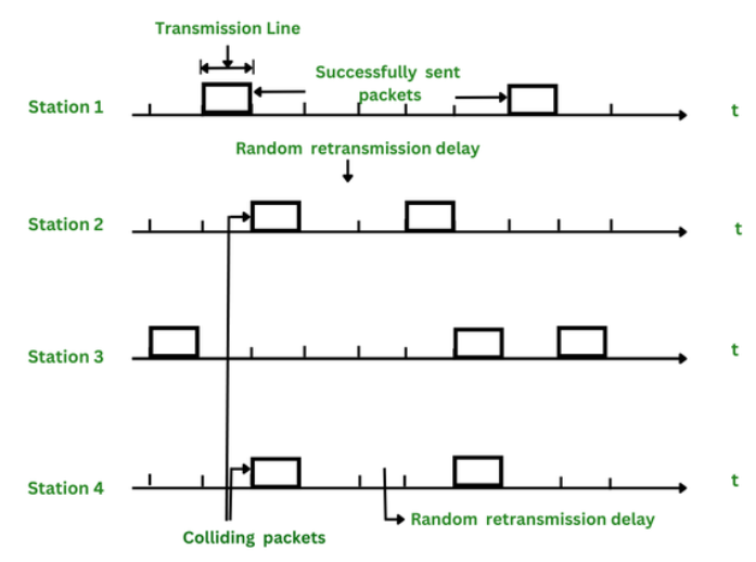
1. Pure ALOHA
https://www.geeksforgeeks.org/what-is-pure-aloha/
https://www.youtube.com/watch?v=WYM9nFYnYAg&list=PLxCzCOWd7aiGFBD2-2joCpWOLUrDLvVV_&index=33
1. Operational Principle
-
Immediate Transmission:
In Pure ALOHA, a device transmits its data frame immediately whenever it has data to send. There is no prior check to see if the channel is free. -
No Synchronization:
There is no global clock or slot synchronization between devices. Each frame is sent at an arbitrary time, which means frames can begin transmission at any moment. -
Collision Occurrence:
Since devices transmit without coordination, if two or more frames overlap in time, a collision occurs. When a collision happens, the frames involved become corrupted.
2. Collision Window and Vulnerability Period
-
Vulnerability Period:
A transmitted frame is vulnerable to collisions during the time period equal to the frame transmission time before and after its start time. This is because another device might start transmitting during this window. -
Total Vulnerable Time:
, where is the frame transmission time.z -
Collision Outcome:
If a collision occurs, none of the overlapping frames are successfully received. Each sender must then retransmit its frame.
3. Handling Collisions
-
Acknowledgment Mechanism:
After transmitting a frame, a sender waits for an acknowledgment (ACK) from the receiver indicating successful receipt.- No ACK Received: If an ACK is not received (due to a collision), the sender assumes the frame was lost or corrupted.
-
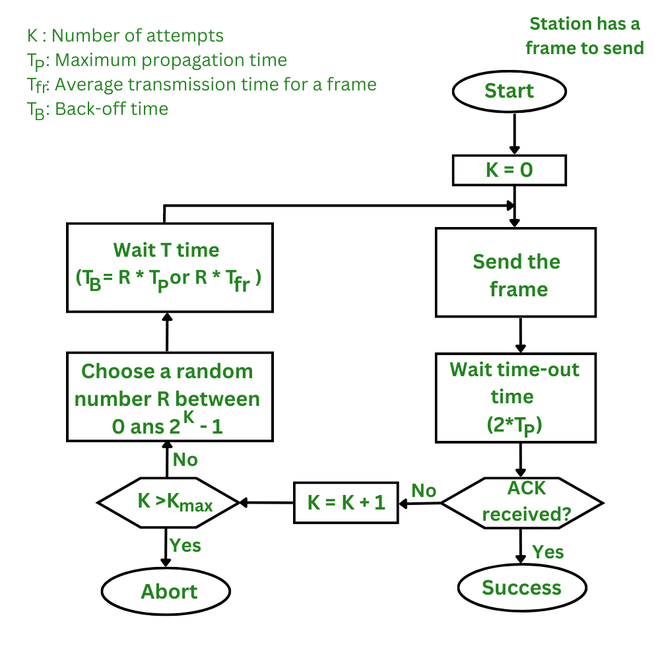
Random Backoff:
Upon detecting a collision (or timeout due to missing ACK), the sender waits for a random period before retransmitting. This random delay helps reduce the probability of repeated collisions.
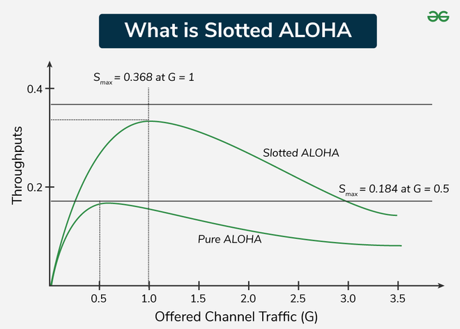
4. Throughput Efficiency
-
Efficiency Calculation:
The maximum theoretical throughput efficiency of Pure ALOHA is relatively low due to the high probability of collisions.- Maximum Efficiency: Approximately 18.4% of the channel's capacity.
This means that only about 18.4% of the transmitted frames are successfully delivered without collision in an ideal scenario.
- Maximum Efficiency: Approximately 18.4% of the channel's capacity.
Explanation:
The efficiency
where
5. Advantages and Disadvantages
Advantages
-
Simplicity:
Pure ALOHA is very easy to implement since devices simply transmit whenever they have data. -
Low Overhead:
There is minimal coordination or control signaling required, reducing protocol complexity.
Disadvantages
-
Inefficient Use of Bandwidth:
The lack of synchronization leads to a high probability of collisions, significantly reducing throughput. -
Poor Performance Under High Load:
As the number of devices increases, the collision probability increases, further degrading performance.
2. Slotted ALOHA
Slotted ALOHA is an enhancement over Pure ALOHA that introduces time synchronization to reduce the likelihood of collisions and improve throughput. In this version, the channel is divided into small, fixed-length time slots and users are only allowed to transmit data at the beginning of each time slot. This synchronization of transmissions reduces the chances of collisions between devices, increasing the overall efficiency of the network.
1. Fundamental Concept
-
Time Division:
In Slotted ALOHA, time is divided into equal-length intervals or slots, each equal to the frame transmission time. -
Synchronized Transmissions:
A device is only allowed to start transmitting at the beginning of a time slot, which helps to avoid partial overlapping of frames.
2. How It Works
Transmission Process
-
Frame Readiness:
When a device has data to send, it waits until the start of the next time slot. -
Transmission at Slot Boundary:
The device transmits its frame right at the beginning of the time slot. -
Collision Occurrence:
-
If two or more devices transmit in the same time slot, a collision occurs, and none of the frames in that slot are received correctly.
-
Since transmissions are synchronized to slot boundaries, collisions can only occur if more than one device transmits in the same slot—not partially overlapping as in Pure ALOHA.
-
Collision Handling
- Acknowledgment and Retransmission:
After transmitting a frame, the sender waits for an acknowledgment (ACK). If an ACK is not received (indicating a collision), the sender waits a random number of time slots before retransmitting the frame.
3. Throughput Efficiency
-
Improved Efficiency:
Slotted ALOHA significantly improves efficiency over Pure ALOHA by reducing the collision window. -
Theoretical Maximum Efficiency:
The maximum throughput for Slotted ALOHA is about 36.8% of the channel capacity. -
Efficiency Formula:
The throughputcan be modeled as: where
is the average number of transmission attempts per time slot. The maximum efficiency occurs when
4. Advantages and Disadvantages
Advantages
-
Higher Throughput:
Synchronizing transmissions reduces the collision probability compared to Pure ALOHA, effectively doubling the maximum throughput. -
Simple Implementation:
Although it requires slot synchronization, the overall protocol remains simple and easy to implement. -
Predictable Timing:
The fixed slot intervals make the system behavior more predictable and easier to analyze.
Disadvantages
-
Time Synchronization Requirement:
All devices must be synchronized to the same clock, which can add complexity to the system design. -
Idle Slots:
If no device transmits during a time slot, that slot is wasted, which may affect overall efficiency under low-load conditions. -
Collisions Still Occur:
If multiple devices choose the same slot, collisions occur; however, the probability is lower compared to unslotted transmissions.
5. Comparison with Pure ALOHA
https://www.youtube.com/watch?v=ggdeb2_z240&list=PLxCzCOWd7aiGFBD2-2joCpWOLUrDLvVV_&index=34
-
Collision Window Reduction:
- Pure ALOHA has a vulnerability period of
(frame time before and after transmission), while Slotted ALOHA restricts potential collisions to within a single time slot.
- Pure ALOHA has a vulnerability period of
-
Efficiency Increase:
- Pure ALOHA offers a maximum throughput of about 18.4%, whereas Slotted ALOHA nearly doubles that efficiency to approximately 36.8%.
6. Practical Considerations
-
Synchronization Mechanisms:
Implementing a reliable synchronization method (using network clocks or beacon signals) is critical for Slotted ALOHA to function properly. -
Traffic Load:
Under heavy traffic conditions, even with slotted access, the probability of collision increases, and careful management of retransmission intervals is necessary. -
Use Cases:
Slotted ALOHA is well-suited for systems where devices are loosely distributed and need a simple yet effective method for medium access control, such as satellite networks or certain wireless sensor networks.
3. CSMA (Carrier Sense Multiple Access Protocol)
https://www.youtube.com/watch?v=IftFvfSywCQ&list=PLxCzCOWd7aiGFBD2-2joCpWOLUrDLvVV_&index=35
https://www.geeksforgeeks.org/carrier-sense-multiple-access-csma/
Carrier Sense Multiple Access (CSMA) is an access control protocol used at the MAC layer that helps multiple nodes share a common communication channel efficiently.
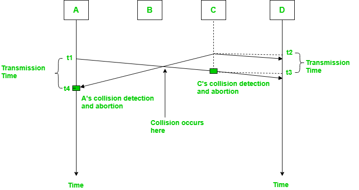
In the diagram, starts sending the first bit of its frame at t1 and since C sees the channel idle at t2, starts sending its frame at t2. C detects A’s frame at t3 and aborts transmission. A detects C’s frame at t4 and aborts its transmission. Transmission time for C’s frame is, therefore, t3-t2 and for A’s frame is t4-t1
So, the frame transmission time (
1. Basic Idea of CSMA
-
Multiple Access:
In a shared medium (like a LAN), several nodes have access to the same channel. CSMA ensures they coordinate their transmissions so that data does not collide excessively. -
Carrier Sensing:
Before a node (say, Node A) transmits its data, it first "senses" the channel to check if it is already in use.-
Local Sensing:
Importantly, a node senses the channel only at its own location. Due to propagation delays, it might not be aware of transmissions far away. -
Objective:
If the channel is busy (i.e., another node is transmitting), Node A holds off to avoid causing a collision. If the channel is idle, it can proceed with its transmission.
-
2. Variations of CSMA Protocols
a. 1-Persistent CSMA
-
Behavior:
- Idle Channel: If the channel is sensed as idle, the node transmits immediately.
- Busy Channel: If the channel is busy, the node continuously senses the channel and transmits as soon as it becomes idle.
-
Trade-offs:
-
Pros: Quick response when the channel becomes free.
-
Cons: If multiple nodes are waiting, they might all sense an idle channel at the same moment and transmit simultaneously, leading to a high probability of collision.
-
b. 0-Persistent CSMA
-
Behavior:
- Idle Channel: If the channel is idle, the node transmits immediately (like 1-persistent).
- Busy Channel: If the channel is busy, the node does not continuously monitor; instead, it waits for a random backoff period before re-sensing the channel.
-
Trade-offs:
-
Pros: The random backoff reduces the chance that multiple nodes will transmit at the same moment once the channel becomes idle.
-
Cons: The waiting period might introduce extra delays even if the channel becomes free sooner.
-
c. P-Persistent CSMA
-
Behavior:
-
Idle Channel: When a node senses the channel is idle, it does not transmit immediately every time. Instead, it transmits with a probability
(where ). -
If Not Transmitting: If the node does not transmit (with probability
), it waits for the next time slot and repeats the process.
-
-
Trade-offs:
-
Pros: This method strikes a balance between immediate transmission and waiting; it reduces collisions compared to 1-persistent CSMA while avoiding excessive delays that might occur with 0-persistent.
-
Cons: The performance is sensitive to the chosen probability value
. An inappropriate value might either increase collisions (if too high) or introduce unnecessary delay (if too low).
-
3. CSMA Variants in Practice
-
CSMA/CD (Collision Detection):
In wired Ethernet networks, CSMA is often combined with collision detection. Nodes listen while transmitting, and if a collision is detected, they abort the transmission and try again after a random back off period. -
CSMA/CA (Collision Avoidance):
In wireless networks (like Wi-Fi), collision detection is challenging due to the nature of radio transmissions. Instead, nodes use collision avoidance strategies, where they wait for a random period even after sensing an idle channel, reducing the chance of collisions.
4. Key Takeaways
-
Carrier Sensing:
Nodes monitor their immediate environment to decide whether to transmit, which helps avoid unnecessary collisions. -
Persistence Protocols:
-
1-Persistent: Aggressive and immediate transmission upon sensing an idle channel—but can cause collisions when many nodes are waiting.
-
0-Persistent: Introduces a random wait if the channel is busy, reducing collisions but potentially causing extra delay.
-
P-Persistent: A balanced approach that transmits with a defined probability when the channel is idle, reducing collision probability while maintaining efficiency.
-
-
Real-World Relevance:
CSMA (and its variations) are fundamental in designing networks that need to support multiple users sharing the same medium, with CSMA/CD and CSMA/CA addressing the challenges specific to wired and wireless environments, respectively.
CSMA/CD (Collision Detection)
CSMA/CD—Carrier Sense Multiple Access with Collision Detection—is an enhancement over basic CSMA. It not only requires nodes to sense the medium before transmitting but also to monitor the medium during transmission to detect if a collision occurs.
1. Fundamentals of CSMA/CD
-
Shared Medium:
Multiple nodes share the same channel. Before transmitting, a node listens (carrier sense) to check if the channel is idle. -
Collision Possibility:
Even if a node senses an idle channel, due to propagation delay it might start transmitting while another node also begins its transmission. Their signals can then collide on the shared medium. -
Collision Detection:
Unlike protocols that rely on acknowledgments (which would add extra traffic), CSMA/CD requires that each node monitors the channel while transmitting.- How It Works:
A node transmits its data and, at the same time, checks if the signal on the medium deviates from what it is sending. If it detects a “collision signal” (a mix of its own signal and another’s), it concludes that a collision has occurred.
- How It Works:
2. Timing and Collision Detection
-
Key Principle:
For a node to detect a collision, it must still be transmitting when the collision effect (the corrupted signal) propagates back to it. -
Propagation Delay:
The delay between when a bit is transmitted and when it reaches another node is called the propagation delay (PD). -
Worst-Case Scenario:
-
Example Scenario:
Consider two nodes, A and B, with a propagation delay of 1 hour between them.-
Timeline:
-
At 12:00 PM, A senses the channel is idle and starts transmitting.
-
B, not yet receiving A’s signal (because of the 1-hour delay), also starts transmitting at 12:00 PM.
-
Their signals collide somewhere between them—say at 12:30 PM.
-
The collision effect then takes 30 minutes to reach A and B.
-
-
Implication:
A will only detect the collision when the corrupted signal arrives—at about 1:00 PM.
Thus, for proper collision detection, the node must transmit for at least 2 × PD (in this example, 2 hours).
-
-
Key Formula:
The transmission time (TT) must satisfy:
Alternatively, if you express the transmission time in terms of message length (L) and bandwidth (R), then:
3. Collision Detection without Acknowledgements
-
No Acknowledgement Overhead:
CSMA/CD avoids using an acknowledgment system for collision detection. If acknowledgments were used, the additional traffic could lead to more collisions and reduced throughput. -
How a Node Detects Collision:
While transmitting, if a node’s transmitter sees a difference between its own output and the signal on the medium (due to superimposition of another node’s transmission), it immediately stops transmitting. This helps conserve bandwidth because the colliding frames are not fully transmitted. -
Immediate Reaction:
The node that detects the collision sends a jam signal (or simply stops transmission) to inform other nodes that a collision has occurred. Then, all nodes back off and try to retransmit after a random delay, reducing the chance of a repeat collision.
4. How Does CSMA/CD Work?
- Step 1: Check if the sender is ready to transmit data packets.
- Step 2: Check if the transmission link is idle.
The sender has to keep on checking if the transmission link/medium is idle. For this, it continuously senses transmissions from other nodes. The sender sends dummy data on the link. If it does not receive any collision signal, this means the link is idle at the moment. If it senses that the carrier is free and there are no collisions, it sends the data. Otherwise, it refrains from sending data. - Step 3: Transmit the data & check for collisions.
The sender transmits its data on the link. CSMA/CD does not use an ‘acknowledgment’ system. It checks for successful and unsuccessful transmissions through collision signals. During transmission, if a collision signal is received by the node, transmission is stopped. The station then transmits a jam signal onto the link and waits for random time intervals before it resends the frame. After some random time, it again attempts to transfer the data and repeats the above process. - Step 4: If no collision was detected in propagation, the sender completes its frame transmission and resets the counters.
How Does a Station Know if Its Data Collide?
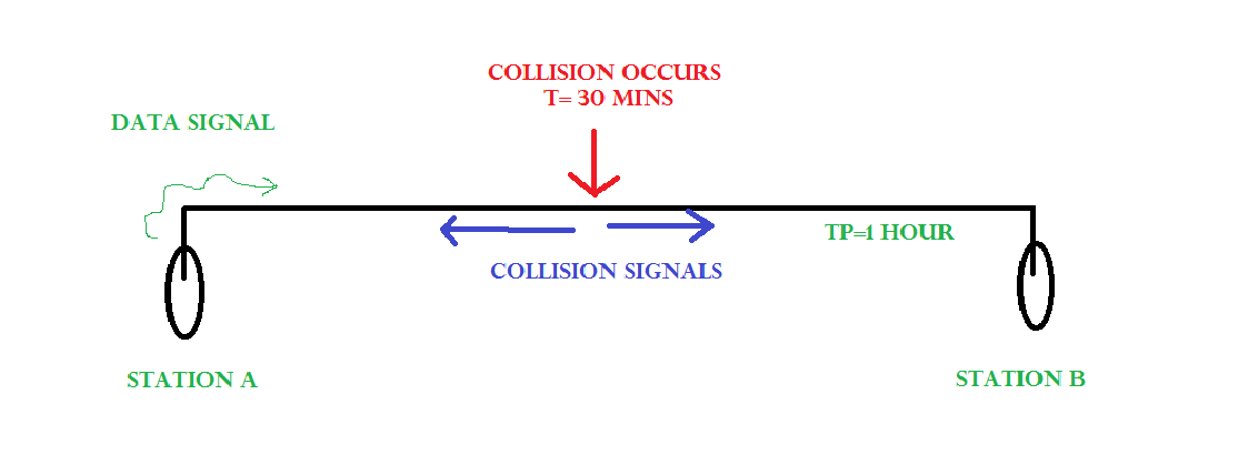
Consider the above situation. Two stations, A & B.
Propagation Time: Tp = 1 hr ( Signal takes 1 hr to go from A to B)
At time t=0, A transmits its data.
        t= 30 mins : Collision occurs.
After the collision occurs, a collision signal is generated and sent to both A & B to inform the stations about the collision. Since the collision happened midway, the collision signal also takes 30 minutes to reach A & B.
Therefore, t=1 hr: A & B receive collision signals.
This collision signal is received by all the stations on that link.
How to Ensure that it is our Station’s Data that Collided? (CA or Collision Avoidance)
For this, Transmission time (Tt) > Propagation Time (Tp) [Rough bound]
This is because we want that before we transmit the last bit of our data from our station, we should at least be sure that some of the bits have already reached their destination. This ensures that the link is not busy and collisions will not occur.
But, above is a loose bound. We have not taken the time taken by the collision signal to travel back to us. For this consider the worst-case scenario.
Consider the above system again.
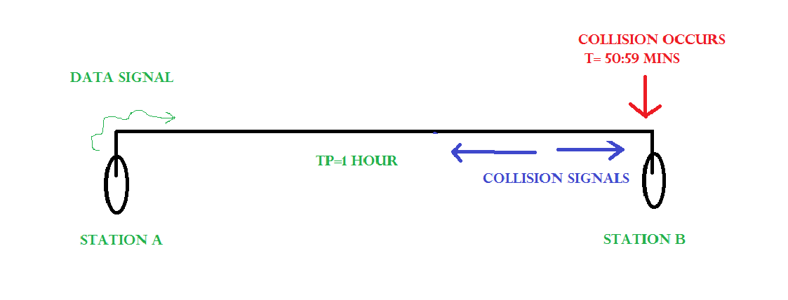
At time t=0, A transmits its data.
        t= 59:59 mins : Collision occurs
This collision occurs just before the data reaches B. Now the collision signal takes 59:59 minutes again to reach A. Hence, A receives the collision information approximately after 2 hours, that is, after 2 * Tp.
Hence, to ensure tighter bound, to detect the collision completely,
Tt > >= 2 * Tp
This is the maximum collision time that a system can take to detect if the collision was of its own data.
What should be the Minimum length of the Packet to be Transmitted?
Transmission Time = Tt = Length of the packet/ Bandwidth of the link
[Number of bits transmitted by sender per second]
Substituting above, we get,
Length of the packet/ Bandwidth of the link>= 2 * Tp
Length of the packet >= 2 * Tp * Bandwidth of the link
Padding helps in cases where we do not have such long packets. We can pad extra characters to the end of our data to satisfy the above condition.
Features of Collision Detection in CSMA/CD
- Carrier Sense: Before transmitting data, a device listens to the network to check if the transmission medium is free. If the medium is busy, the device waits until it becomes free before transmitting data.
- Multiple Access: In a CSMA/CD network, multiple devices share the same transmission medium. Each device has equal access to the medium, and any device can transmit data when the medium is free.
- Collision Detection: If two or more devices transmit data simultaneously, a collision occurs. When a device detects a collision, it immediately stops transmitting and sends a jam signal to inform all other devices on the network of the collision. The devices then wait for a random time before attempting to transmit again, to reduce the chances of another collision.
- Backoff Algorithm: In CSMA/CD, a backoff algorithm is used to determine when a device can retransmit data after a collision. The algorithm uses a random delay before a device retransmits data, to reduce the likelihood of another collision occurring.
- Minimum Frame Size: CSMA/CD requires a minimum frame size to ensure that all devices have enough time to detect a collision before the transmission ends. If a frame is too short, a device may not detect a collision and continue transmitting, leading to data corruption on the network.
Advantages of CSMA/CD
- Simple and widely used: CSMA/CD is a widely used protocol for Ethernet networks, and its simplicity makes it easy to implement and use.
- Fairness: In a CSMA/CD network, all devices have equal access to the transmission medium, which ensures fairness in data transmission.
- Efficiency: CSMA/CD allows for efficient use of the transmission medium by preventing unnecessary collisions and reducing network congestion.
Disadvantages of CSMA/CD
- Limited Scalability: CSMA/CD has limitations in terms of scalability, and it may not be suitable for large networks with a high number of devices.
- Vulnerability to Collisions: While CSMA/CD can detect collisions, it cannot prevent them from occurring. Collisions can lead to data corruption, retransmission delays, and reduced network performance.
- Inefficient Use of Bandwidth: CSMA/CD uses a random backoff algorithm that can result in inefficient use of network bandwidth if a device continually experiences collisions.
- Susceptibility to Security Attacks: CSMA/CD does not provide any security features, and the protocol is vulnerable to security attacks such as packet sniffing and spoofing.
CSMA/CA (Collision Avoidance)
https://www.youtube.com/watch?v=reQ938TeFHM&list=PLxCzCOWd7aiGFBD2-2joCpWOLUrDLvVV_&index=37
🌐 Why CSMA/CA Exists
In wired networks, like Ethernet, we use CSMA/CD (Carrier Sense Multiple Access with Collision Detection). But in wireless networks (Wi-Fi, IEEE 802.11), we use CSMA/CA, because:
-
In wireless, it's hard to detect collisions — signals weaken as they travel, so a node can't reliably "hear" other transmissions or detect overlapping energy like in wired systems.
-
So instead of detecting collisions after they happen (like CD), CA tries to avoid collisions in the first place.
🚦 How CSMA/CA Works (Step-by-Step Gist)
-
Sense the Channel (Carrier Sensing):
- The device (node) checks if the channel is idle (no one else is talking).
- If it's busy, it keeps waiting until it's free.
-
Wait for a While (Inter Frame Space or IFS):
- Even after the channel seems idle, the device waits a little longer
- Why? Maybe another station is about to start sending, and this wait gives them a chance to go first — to avoid collision.
-
Random Backoff (Contention Window):
- The device picks a random number
Rin a growing window:0 to (2^K - 1)whereKis the number of previous failed attempts. - It waits for
R * SlotTimebefore trying to send — this spreads out attempts among devices to reduce collision chances.
- The device picks a random number
-
RTS/CTS Handshake (optional but common in Wi-Fi):
- Device sends an RTS (Ready To Send) signal to the access point.
- Access point responds with CTS (Clear To Send).
- Other devices hear the CTS and know they must stay silent for a while — this avoids hidden terminal issues.
-
Data Transmission:
- If the device gets CTS, it sends the actual data.
- If it gets an ACK (acknowledgment), it knows the transmission was successful.
-
If no ACK is received:
- The device assumes a collision happened.
- It increases
Kand tries again with a larger backoff.
🧠 Key Differences from CSMA/CD:
| Feature | CSMA/CD (Wired) | CSMA/CA (Wireless) |
|---|---|---|
| Type | Collision Detection | Collision Avoidance |
| Medium | Wired LAN | Wireless LAN (Wi-Fi) |
| Collision Handling | Detect collision via signal energy | Avoid collisions via waiting & RTS/CTS |
| Acknowledgment | Not always needed | ACK is mandatory to confirm success |
| RTS/CTS | Not used | Often used to avoid hidden terminals |
🧠 Simple Analogy
Imagine you're in a classroom:
-
CSMA/CD: You start talking, and if someone else talks at the same time, you both realize and stop.
-
CSMA/CA: You wait, check if the room is quiet, then raise your hand (RTS), wait for the teacher to say "Go ahead" (CTS), and then you talk — to make sure nobody else tries to speak at the same time.