Module 3 -- Network Layer -- Computer Networks
Index
- Introduction to the Network Layer
- Switching
- Logical Addressing and IPv4 vs IPv6
- Physical Address vs Logical Address in Networking
- 2. IPv4 (Internet Protocol Version 4)
- 3. IPv6 (Internet Protocol Version 6)
- Address Mapping and it's Protocols
- 1. ARP (Address Resolution Protocol)
- 2. RARP (Reverse ARP) (or Inverse ARP)
- 3. BOOTP Protocol (Bootstrap Protocol)
- 4. DHCP Protocol
- Routing, Forwarding, Unicast Routing and it's protocols
- 1. Distance Vector Routing
- 2. Link State Routing
Introduction to the Network Layer
-
Purpose:
The network layer is responsible for the delivery of packets from the source host to the destination host across multiple networks. It manages routing, addressing, and packet forwarding to ensure data reaches its target. -
Key Functions:
-
Routing: Determining the best path for data to travel through interconnected networks.
-
Forwarding: Moving packets from an incoming link to the appropriate outgoing link.
-
Logical Addressing: Assigning unique addresses (e.g., IP addresses) to each host on the network.
-
1. Host-to-Host (Source-to-Destination) Delivery
-
Purpose:
The primary job of the Network Layer is to deliver packets from the originating host to the destination host, even if they are in different networks. This process is also called machine-to-machine delivery. -
Logical Addressing (IP Addressing):
-
Logical Address: Unlike the Data Link Layer that uses physical (MAC) addresses, the Network Layer uses logical addresses, typically IP addresses.
-
IP Address Structure:
An IP address is made up of two parts:-
Network ID: Indicates which network the host belongs to.
-
Host ID: Identifies the specific machine within that network.
-
-
Function:
By including the source and destination IP addresses in each packet, the Network Layer ensures that routers and other network devices know both where the packet comes from and where it should be delivered.
-
2. Routing
-
What is Routing?
Routing is the process of determining the best path for data to travel from the source to the destination across interconnected networks. -
How Routing Works:
-
Routers:
Devices such as routers (and sometimes intelligent switches or even firewalls) work at the Network Layer. When a packet arrives at a router, the router examines the destination IP address and uses routing tables and algorithms to decide which outgoing interface will best forward the packet. -
Routing Protocols:
There are several routing protocols that help build and maintain these routing tables:-
RIP (Routing Information Protocol): Uses distance vector routing.
-
OSPF (Open Shortest Path First): Uses link-state routing to determine the shortest path.
-
Others: Protocols like BGP (Border Gateway Protocol) for inter-domain routing.
-
-
Path Selection:
Routers choose the shortest or most efficient route based on various metrics (like hop count, cost, or delay), ensuring that packets reach their destination in a timely manner.
-
3. Fragmentation
-
Why Fragmentation is Needed:
Different networks may have varying maximum transmission unit (MTU) sizes. If a packet from the source is larger than the MTU of an intermediate network, the router must break (fragment) the packet into smaller pieces. -
How Fragmentation Works:
-
Breaking Down Packets:
The original packet is divided into smaller fragments that fit within the MTU constraints of the intermediate network. -
Reassembly:
At the destination, these fragments are reassembled to reconstruct the original packet. -
Importance:
Fragmentation ensures that large packets can be transmitted across networks that cannot handle them in one piece, preventing data loss or the need for retransmission.
-
4. Congestion Control (to a Lesser Extent)
-
Purpose:
Although congestion control is more commonly handled by the Transport Layer, the Network Layer also has mechanisms to help manage network congestion. -
Techniques and Protocols:
-
Leaky Bucket/Token Bucket Methods:
These methods are used to regulate the rate at which packets are transmitted into the network, preventing overwhelming traffic. -
ICMP/IGMP:
In some cases, protocols like ICMP (Internet Control Message Protocol) may be used to send control messages that help manage or indicate congestion. -
Role:
These techniques help ensure that the network does not become overloaded with traffic, thereby maintaining a level of efficiency and reliability in packet delivery.
-
Switching
Switching is a fundamental process in networking that directs data from a source to its destination. It involves making decisions about which path or channel a data packet should take as it moves through the network.
1. What is Switching?
Switching is the process of transferring data packets between different network segments or devices. It determines the route that data takes from the sender to the receiver. The key goals of switching are:
-
Efficient Resource Use: Maximizing the use of available network bandwidth.
-
Low Latency: Ensuring data is delivered as quickly as possible.
-
Flexibility: Allowing multiple connections to coexist and share the same physical medium.
2. Types of Switching
https://www.geeksforgeeks.org/what-is-switching/
There are three primary types of switching techniques, each with its own method and applications:
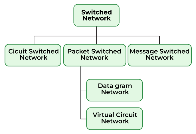
A. Circuit Switching
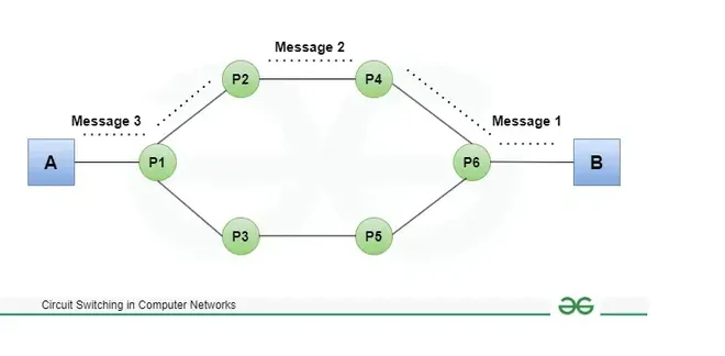
-
Concept:
A dedicated communication path is established between the sender and receiver before any data is transmitted. -
Operation:
-
Connection Setup: A circuit (or channel) is reserved for the duration of the communication session.
-
Continuous Transmission: Once established, the circuit is exclusively used by the communicating parties.
-
Teardown: The circuit is released once the communication ends.
-
-
Example:
Traditional telephone networks use circuit switching, where a dedicated line is established for the duration of the call. -
Pros and Cons:
-
Pros: Guaranteed bandwidth and predictable performance.
-
Cons: Inefficient utilization of resources if the dedicated channel remains idle during periods of silence or low data transfer.
-
B. Packet Switching
-
Concept:
This technique requires the data to be broken down into smaller components, data frames, or packets. These data frames are then transferred to their destinations according to the available resources in the network at a particular time. -
Operation:
-
Dynamic Routing: Each packet is routed independently based on current network conditions.
-
Reassembly: The destination device reassembles the packets into the original message.
-
-
Types of Packet Switching:
-
Datagram Switching: In Datagram Packet switching, each data frame is taken as an individual entity and thus, they are processed separately. Here, no connection is established before data transmission occurs. Although this approach provides flexibility in data transfer, it may cause a loss of data frames or late delivery of the data frames.
-
Virtual-Circuit Switching: A logical path is established before transmission (similar to a circuit), but data is still sent in packets. All packets follow the same route, which simplifies reassembly.
-
-
Examples:
The Internet is based on packet switching, where protocols like IP (Internet Protocol) manage packet delivery. -
Pros and Cons:
-
Pros: Efficient utilization of network resources since packets can take alternate routes, and resources are shared among many users.
-
Cons: Variability in delay (jitter) and potential for packet loss or out-of-order delivery.
-
C. Virtual-Circuit Switching
-
Concept:
This technique combines elements of both circuit switching and packet switching. -
Operation:
-
Setup Phase: A virtual circuit is established between the sender and receiver. A unique identifier is assigned to the circuit.
-
Packet Transmission: Packets are sent along the pre-determined path. Although the physical medium is shared, the logical path is fixed for the duration of the session.
-
Teardown: The virtual circuit is terminated after the session ends.
-
-
Examples:
Technologies like Frame Relay and Asynchronous Transfer Mode (ATM) use virtual-circuit switching. -
Pros and Cons:
-
Pros: Combines the reliability and ordered delivery of circuit switching with the flexibility of packet switching.
-
Cons: Requires additional overhead to set up and maintain the virtual circuit, and is less flexible in adapting to sudden network changes compared to pure packet switching.
-
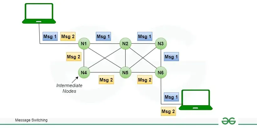
D. Message Switching
This is an older switching technique that has become obsolete. In message switching technique, the entire data block/message is forwarded across the entire network thus, making it highly inefficient.
3. How Switching Works: Key Components and Processes
A. Switching Devices
-
Switches:
Operate at the data link layer (Layer 2) of the OSI model. They use MAC addresses to forward data within a local area network (LAN). -
Routers:
Operate at the network layer (Layer 3) and are responsible for routing packets between different networks using IP addresses. -
Multilayer Switches:
Combine functionalities of both switches and routers, capable of making decisions based on both MAC and IP addresses.
B. Switching Techniques
-
Store-and-Forward:
The switch receives the entire frame, checks it for errors, and then forwards it. This method ensures error-free transmission but introduces some delay. -
Cut-Through:
The switch starts forwarding the frame as soon as it reads the destination address, reducing latency at the cost of error checking. -
Fragment-Free:
A compromise between store-and-forward and cut-through, where the switch reads a portion of the frame (enough to check for most collisions) before forwarding.
C. Decision Process
-
Address Learning:
Switches build a table of MAC addresses by examining incoming frames. This table helps in determining which port to forward the frame. -
Forwarding:
Based on the destination address, the switch sends the frame out the appropriate port, or floods the frame to all ports if the destination is unknown.
4. Practical Considerations and Applications
-
Scalability:
Packet switching and virtual-circuit switching are generally more scalable for large, dynamic networks like the Internet. -
Resource Utilization:
Packet switching makes efficient use of network bandwidth by allowing multiple communications to share the same channel. -
Quality of Service (QoS):
Virtual-circuit switching can offer more predictable performance, which is important for real-time applications like voice and video conferencing. -
Network Design:
Understanding the strengths and limitations of each switching method helps in designing networks that balance performance, reliability, and cost.
Logical Addressing and IPv4 vs IPv6
1. Overview of Logical Addressing
-
Purpose:
Logical addresses allow devices to be uniquely identified on a network and facilitate the routing of packets between different networks. They provide a layer of abstraction over physical addressing, enabling scalable and hierarchical network design. -
How It Works:
-
Assignment: Each device is assigned a unique logical address.
-
Routing: Routers use these addresses to determine the best path for a packet, making decisions based on network prefixes and routing tables.
-
Independence: Logical addresses can be reassigned or reorganized without changing the underlying physical network.
-
Physical Address vs Logical Address in Networking
https://www.geeksforgeeks.org/what-is-physical-address-and-logical-address-in-networking/
A physical address is a unique identifier given to network interfaces for communication over a physical network segment. A logical address is a unique address assigned to each networked device to identify its location and enable routing
What is a Physical Address?
The physical address is also known as the MAC (Media Access Control) address or link address. It is the address of a node which is defined by its LAN or WAN. It is used by the data link layer and is the lowest level of addresses. MAC address is the unique address of a device. The size of a physical address is 48 bits (6 bytes). Below is the format for representing a physical address:
XX : XX : XX : YY : YY : YY, where 1 octant = 8 bits.
Example:
16 : 1A : BB : 6F : 90 : E5
Note: Sometimes an octant is also called octet.
In the context of IP addresses (specifically IPv4), an octet refers to each of the four 8-bit (or 1 byte) sections of an IP address, separated by periods.
The first 24 bits of a MAC address XX : XX: XX is decided by OUI (Organizationally Unique Identifier). It represents the identity of the manufacturer. The next 24 bits of a MAC address YY : YY : YY represents the unique identity of the device. It is assigned by the manufacturer. They represent NIC (Network Interface Card).
So the MAC address is basically :
manufacturer : device
each segment having 24 bits each. So the total size of a physical address is 48 bits.
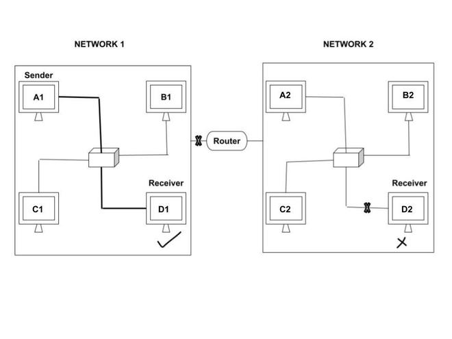
In the above diagram, we can see that there are two networks - Network 1 and Network 2. A1 is the sender and there are two receivers - D1 and D2. In case of physical address, receiver D1 receives the data but receiver D2 is unable to receive data. This is because receiver D2 does not belong to the same network as the sender A1 belongs to. Physical address can only be passed in the same network and not in different networks. The purpose of using Physical address is to identify devices in the same network.
Advantages
- Physical address can uniquely identify devices and deliver data packets accurately.
- We can restrict access to any network by allowing only those devices which have the authorized MAC addresses to connect. Thus, it can also be used for network security.
Disadvantages
- MAC addresses can be easily spoofed. Thus, the devices can easily gain unauthorized access to a network.
- As physical addresses cannot traverse through the routers therefore they can only be used in local networks and not between different networks.
Logical Address
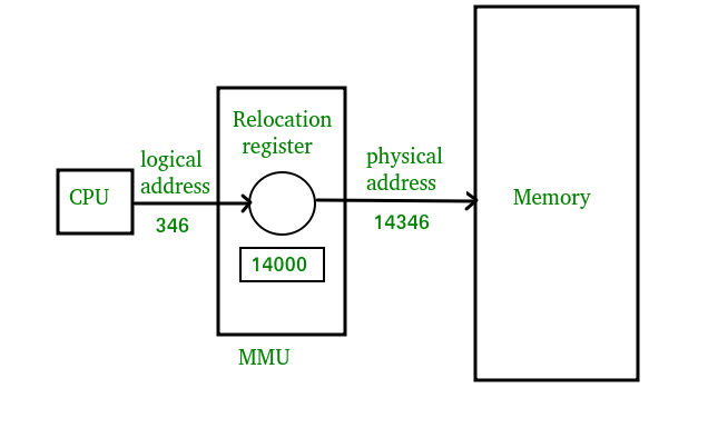
As we have seen previously in Operating Systems, Logical Addresses are purely for the CPU to allocate data into the registers/virtual memory which is then translated to physical address by a translation-lookaside buffer of the MMU to send/retrieve data to the actual physical memory.
In the context of Computer Networking, the concept stays similar:
Logical address also referred to as IP (Internet Protocol) address is an universal addressing system. It is used in the Network layer. This address facilitates universal communication that are not dependent on the underlying physical networks. There are two types of IP addresses - IPv4 and IPv6.
The size of IPv4 is 32 bits. For example ,
192 : 180 : 210 where, 1 octant = 8 bits.
So the logical address space of IPv4 is
The size of IPv6 is 128 bits. For example ,
1C18 : 1B32 : C450 : 62A5 : 34DC : AE24 : 15BC : 6A5D where , 1 octant = 16 bits.
So the logical address space of IPv6 is
As you can see this is the main difference in Logical Addresses from Physical Addresses.
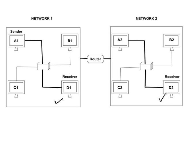
In the above diagram , we can see that there are two networks - Network 1 and Network 2. A1 is the sender and there are two receivers - D1 and D2. In case of logical address, receiver D1 as well as D2 receives the data. This is because logical address can be passed in different networks. The purpose of using logical address is to send the data across networks.
Advantages
- Logical address can be used in different networks because they can traverse through routers.
- They can handle a number devices and networks. Even if the number of devices and network increases, the logical address is able to handle all them very easily. Thus, they are highly scalable.
Disadvantages
- Internet Protocol is vulnerable to attacks such as hacking, phishing etc. and there can be data loss.
- It lacks privacy. The data which is moving through the packets can be intercepted, traced and monitored by unauthorized entities.
Differences between Physical Address and Logical Address
| Physical Address | Logical Address |
|---|---|
| Physical Address is the address of a node which is defined by its LAN or WAN | Logical address also referred to as IP (Internet Protocol) address is an universal addressing system |
| Physical Address is computed bu MMU. | Logical Address is generated by CPU. |
| Found on Data Link Layer. | Found on Network Layer. |
| Format is 48-bit address in hexadecimal. | Format is IPv4: 32-bit IPv6: 128-bit |
| Physical address is not visible to users. | Logical address is visible to users. |
2. IPv4 (Internet Protocol Version 4)
https://www.geeksforgeeks.org/what-is-an-ip-address/
Address Format
-
32-bit Address:
IPv4 addresses are 32 bits long and are typically written in dotted-decimal notation, for example:
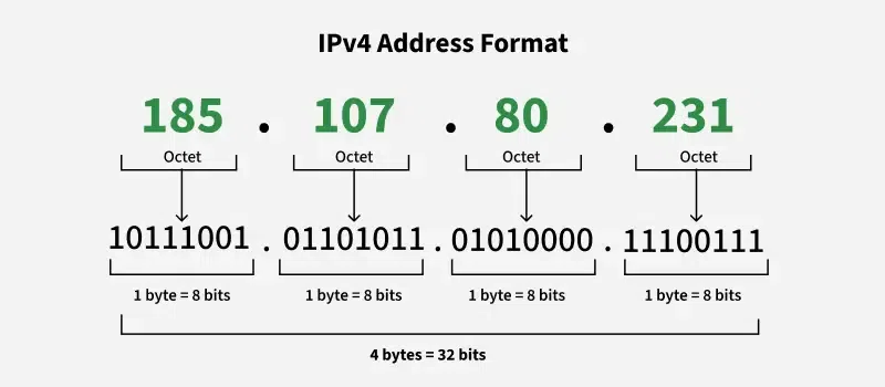
192.168.1.1- Four Octets: Each octet represents eight bits, or a byte, and can take a value from 0 to 255. This range is derived from the possible combinations of eight bits (2^8 = 256 combinations).
- Example of IPv4 Address: 192.168.1.1
- 192 is the first octet
- 168 is the second octet
- 1 is the third octet
- 1 is the fourth octet
-
Structure:
An IPv4 address consists of two parts:-
Network Portion: Identifies the network.
-
Host Portion: Identifies a specific device (host) within that network.
-
-
Subnet Masks:
Subnet masks (e.g.,255.255.255.0) are used to distinguish the network portion from the host portion, allowing for subnetting—dividing a larger network into smaller, manageable segments.
Advantages and Limitations
-
Advantages:
-
Simplicity and Widespread Adoption: IPv4 is well understood and has been the backbone of the Internet for decades.
-
Mature Infrastructure: Tools, protocols, and network devices are optimized for IPv4.
-
-
Limitations:
-
Address Exhaustion: With only about 4.3 billion addresses, IPv4 has faced significant challenges due to the rapid expansion of internet-connected devices.
-
Fragmentation and Routing Complexity: As networks grew, managing routing tables and fragmentation became more complex.
-
3. IPv6 (Internet Protocol Version 6)
Address Format
-
128-bit Address:
IPv6 addresses are 128 bits long, dramatically increasing the available address space. They are written in hexadecimal notation and separated by colons, for example:2001:0db8:85a3:0000:0000:8a2e:0370:7334 -
Address Abbreviation:
-
Leading zeros in a group can be omitted.
-
Consecutive groups of zeroes can be replaced by a double colon , but only once in an address.
-
-
Structure:
IPv6 addresses are typically divided into:-
Global Routing Prefix: Identifies a specific network or organization.
-
Subnet ID: Allows further segmentation within an organization.
-
Interface Identifier: Uniquely identifies a device on a subnet.
-
Advantages and Improvements
-
Vast Address Space:
With 2^128 possible addresses, IPv6 virtually eliminates address exhaustion. -
Simplified Header Structure:
IPv6 headers are designed for more efficient routing by simplifying fields and reducing processing overhead. -
Built-in Security and Mobility:
Features like IPsec (for encryption and authentication) are built into the IPv6 protocol. It also has improved support for mobile devices. -
Autoconfiguration:
IPv6 supports stateless address autoconfiguration (SLAAC), allowing devices to configure their own addresses without needing a DHCP server.
4. Comparison: IPv4 vs. IPv6
| Feature | IPv4 | IPv6 |
|---|---|---|
| Address Length | 32 bits (dotted-decimal notation) | 128 bits (hexadecimal notation) |
| Address Space | ~4.3 billion addresses | Vast address space (2^128 addresses) |
| Header Complexity | More fields, some optional fragmentation | Simplified header with fixed fields, no fragmentation at routers |
| Security | IPsec is optional | IPsec is a fundamental part of the protocol |
| Configuration | Typically requires DHCP or manual assignment | Supports stateless autoconfiguration (SLAAC) and DHCPv6 |
| Mobility | Limited built-in support for mobile devices | Enhanced mobility support with streamlined protocols |
5. Practical Implications and Use Cases
-
IPv4:
-
Widely deployed in existing networks, data centers, and many home networks.
-
Continued use in legacy systems and regions where IPv6 adoption is still in progress.
-
-
IPv6:
-
Designed to meet the growing demand for internet-connected devices.
-
Increasingly deployed by ISPs, large organizations, and in new network infrastructure projects.
-
Offers long-term scalability and improved efficiency for emerging technologies like the Internet of Things (IoT).
-
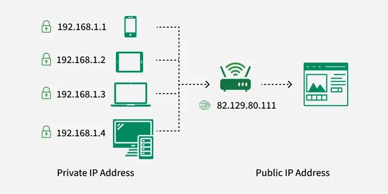
Based on Usage: Public vs Private IP Addresses
Public IP Addresses
A Public IP address is assigned to every device that directly accesses the internet. This address is unique across the entire internet. Here are the key characteristics and uses of public IP addresses:
- Uniqueness: Each public IP address is globally unique. No two devices on the internet can have the same public IP address at the same time.
- Accessibility: Devices with a public IP address can be accessed directly from anywhere on the internet, assuming no firewall or security settings block the access.
- Assigned by ISPs: Public IP addresses are assigned by Internet Service Providers (ISPs). When you connect to the internet through an ISP, your device or router receives a public IP address.
- Types: Public IP addresses can be static (permanently assigned to a device) or dynamic (temporarily assigned and can change over time).
Private IP Addresses
Private IP addresses are used within private networks (such as home networks, office networks, etc.) and are not routable on the internet. This means that devices with private IP addresses cannot directly communicate with devices on the internet without a translating mechanism like a router performing Network Address Translation (NAT). Key features include:
- Not globally unique: Private IP addresses are only required to be unique within their own network. Different private networks can use the same range of IP addresses without conflict.
- Local communication: These addresses are used for communication between devices within the same network. They cannot be used to communicate directly with devices on the internet.
- Defined ranges: The Internet Assigned Numbers Authority (IANA) has reserved specific IP address ranges for private use:
- IPv4: 10.0.0.0 to 10.255.255.255, 172.16.0.0 to 172.31.255.255, 192.168.0.0 to 192.168.255.255
- *IPv6: Addresses starting with FD or FC
Based on Assignment Method (Static vs. Dynamic)
Static IP Addresses:
- These are permanently assigned to a device, typically important for servers or devices that need a constant address.
- Reliable for network services that require regular access such as websites, remote management.
Dynamic IP Addresses:
- Temporarily assigned from a pool of available addresses by the Dynamic Host Configuration Protocol (DHCP).
- Cost-effective and efficient for providers, perfect for consumer devices that do not require permanent addresses.
Address Mapping and it's Protocols
Address mapping protocols are crucial for resolving logical addresses (IP addresses) to physical addresses (MAC addresses) so that packets can be correctly forwarded on a local network.
1. ARP (Address Resolution Protocol)
https://www.geeksforgeeks.org/arp-protocol/
1. Purpose of ARP
- Mapping Logical to Physical Addresses:
ARP is used to map an IP address (logical address) to its corresponding MAC address (physical address) on a local network. This is crucial because while IP addresses are used for routing packets across networks, actual data transfer on the local network is done using MAC addresses.
2. How ARP Works
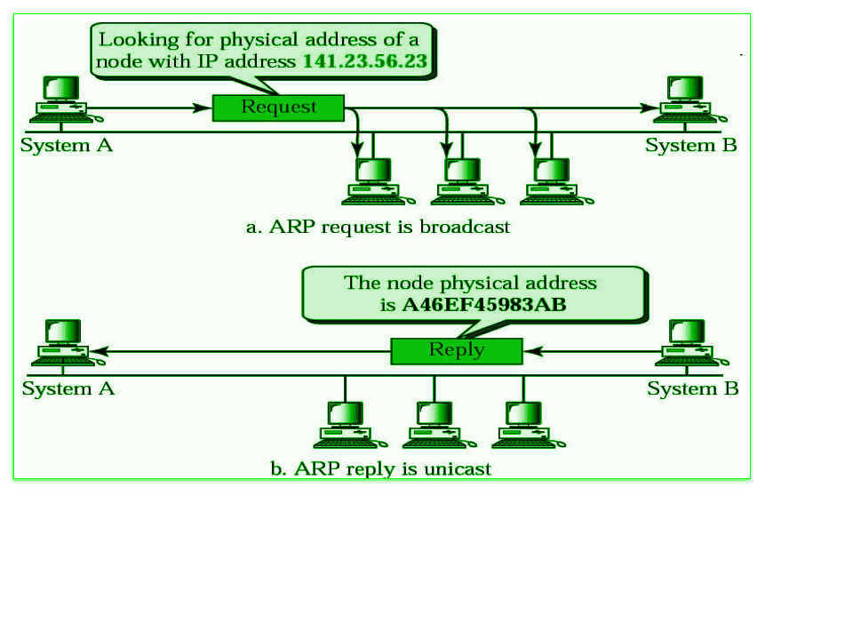
ARP Request
-
Broadcasting:
When a device (say, Host A) wants to send data to another device on the same LAN but only knows the destination’s IP address, it broadcasts an ARP Request to all devices in the local network. This request asks, "Who has IP address X? Please send your MAC address." -
Packet Contents:
The ARP Request packet typically contains:- Sender's IP and MAC addresses.
- Target's IP address (the one being queried).
- A broadcast MAC address as the destination address, ensuring all devices on the LAN receive it.
ARP Reply
-
Unicast Response:
The device with the matching IP address (say, Host B) responds with an ARP Reply. This reply is unicast directly to the requesting device and includes Host B's MAC address. -
Cache Update:
Upon receiving the ARP Reply, Host A updates its ARP cache (a temporary table mapping IP addresses to MAC addresses) and can now send the data frame to Host B using the retrieved MAC address.
3. ARP Cache and Maintenance
-
Caching:
To avoid flooding the network with ARP Requests for every packet, devices store recently learned IP-to-MAC mappings in an ARP cache. -
Timeouts:
Entries in the ARP cache are temporary and are purged after a set period (typically minutes) to ensure outdated mappings are removed.
4. Issues and Considerations
-
ARP Spoofing/Poisoning:
Since ARP lacks authentication, it is vulnerable to security attacks such as ARP spoofing, where an attacker sends falsified ARP Replies to associate its MAC address with the IP address of another device. -
Broadcast Nature:
ARP Requests are broadcasted to every device on the LAN, which can increase network traffic in large networks. However, ARP Replies are unicast, reducing overall traffic. -
Layer 2/Layer 3 Interaction:
ARP operates between the Data Link layer (Layer 2) and the Network layer (Layer 3), acting as a bridge that translates logical addresses into physical addresses needed for actual data delivery.
Types of ARP
There are four types of ARP protocol they are as follows:-
- Proxy ARP
- Gratuitous ARP
- Reverse ARP
- Inverse ARP
1. Proxy ARP
This is a technique through which proxy ARP in a network can answer ARP queries of IP addresses that are not in that network. That is, if we understand it in simple language, the Proxy server can also respond to queries of IP-address of other networks.
Through this we can fool the other person because instead of the MAC address of the destination device, the MAC address of the proxy server is used and the other person does not even know.
2. Gratuitous ARP
This is an arp request of a host, which we use to check duplicate ip-address. And we can also use it to update the arp table of other devices. That is, through this we can check whether the host is using its original IP-address, or is using a duplicate IP-address.
3. Reverse ARP
This is also a networking protocol, which we can use through client computer. That is, it is used to obtain information about one's own network from the computer network.
4. Inverse ARP (InARP)
Inverse ARP, it is the opposite of ARP, that is, we use it to know the IP address of our device through MAC Address, that is, it is such a networking technology, through this we convert MAC Address into IP address. It is mainly used in ATM machines.
Advantages of ARP Protocol
There are many Advantages of ARP protocol but below we have told you about some important advantages.
- By using this protocol we can easily find out the MAC Address of the device.
- There is no need to configure the end nodes at all to extract the MAC address through this protocol.
- Through this protocol we can easily translate IP address into MAC Address.
- There are four main types of this protocol. Which we can use in different ways, and they prove to be very help
2. RARP (Reverse ARP) (or Inverse ARP)
1. Purpose of RARP
-
Mapping Physical to Logical Addresses:
RARP is designed to perform the reverse function of ARP. While ARP maps an IP (logical) address to a MAC (physical) address, RARP allows a device that knows its own MAC address—but not its IP address—to discover its corresponding IP address. -
Typical Use Case:
RARP was primarily used by diskless workstations or devices that do not have permanent storage for configuration data. At boot time, these devices use RARP to request and receive their IP address from a RARP server.
2. How RARP Works
RARP Request
-
Broadcast Request:
When a device (e.g., a diskless workstation) boots up, it doesn't have an IP address yet. It sends out a RARP Request as a broadcast message, including its own MAC address. -
Packet Contents:
The RARP Request contains:-
The sender’s MAC address (the only available identifier).
-
A request for the RARP server to provide the corresponding IP address.
-
RARP Reply
-
Unicast Response:
A RARP server, which maintains a table mapping MAC addresses to IP addresses, receives the request and looks up the MAC address. -
Providing the IP Address:
The server sends a RARP Reply, which is a unicast message containing the IP address that corresponds to the requesting device's MAC address.
3. RARP Server and Operation
-
Server Role:
The RARP server is typically configured on a network to maintain a mapping between MAC addresses and IP addresses. When a device sends out a RARP Request, the server matches the MAC address and returns the appropriate IP address. -
Bootstrapping:
Once the device receives its IP address via the RARP Reply, it can configure its network interface and proceed with normal operation, including contacting additional servers for further configuration (if needed).
4. Limitations and Evolution
-
Limited Functionality:
RARP was limited in that it only provided the IP address. It didn't supply other configuration details, such as the subnet mask, default gateway, or DNS server addresses. -
Evolution to More Advanced Protocols:
Due to these limitations, RARP has largely been replaced by protocols like BOOTP (Bootstrap Protocol) and DHCP (Dynamic Host Configuration Protocol). These protocols not only provide an IP address but also offer a more comprehensive configuration, including additional network parameters. -
Security Considerations:
Like ARP, RARP lacks robust security features. In modern networks, the more feature-rich and secure DHCP is preferred.
Disadvantages of RARP
- The RARP server must be located within the same physical network.
- The computer sends the RARP request on very cheap layer of the network. Thus, it’s unattainable for a router to forward the packet because the computer sends the RARP request on very cheap layer of the network.
- The RARP cannot handle the subnetting process because no subnet masks are sent. If the network is split into multiple subnets, a RARP server must be available with each of them.
- It isn’t possible to configure the PC in a very modern network.
- It doesn’t fully utilize the potential of a network like Ethernet.
3. BOOTP Protocol (Bootstrap Protocol)
BOOTP is a more advanced version of RARP.
1. Purpose of BOOTP
-
Configuration for Diskless Workstations:
BOOTP was developed to help diskless workstations (or devices without local storage for configuration) automatically obtain essential network parameters needed for startup. -
Automatic Network Configuration:
It allows a device (the BOOTP client) to request and receive its IP address and other configuration details from a BOOTP server, eliminating the need for manual configuration.
2. Key Functions of BOOTP
-
IP Address Assignment:
The BOOTP server maintains a mapping between a client's hardware (MAC) address and its assigned IP address. When a client boots up, it sends a request including its MAC address, and the server responds with the corresponding IP address. -
Provisioning Additional Configuration:
In addition to the IP address, BOOTP can provide other configuration details such as:- Subnet mask
- Default gateway (router)
- DNS server addresses
- Boot file name and server (for network booting)
-
Network Booting:
BOOTP is commonly used in scenarios where the client needs to download a boot image or operating system from a server to start up.
3. How BOOTP Works
A. BOOTP Client Process
-
Client Initialization:
-
When a device boots up, it doesn’t have an IP address.
-
The client creates a BOOTP Request packet that contains its MAC address and possibly a requested boot file name.
-
-
Broadcast Request:
-
Since the client doesn't have an IP address yet, it broadcasts the BOOTP Request on the local network.
-
The broadcast ensures that any BOOTP server on the network can receive the request.
-
B. BOOTP Server Process
-
Request Reception:
-
A BOOTP server listens for BOOTP Requests.
-
When it receives a request, it checks its configuration table for a matching MAC address.
-
-
Formulating a Response:
- If a match is found, the server prepares a BOOTP Reply packet that includes the assigned IP address and any additional network configuration information (like the subnet mask, default gateway, and boot file details).
-
Sending the Reply:
- The BOOTP Reply is sent as a unicast message directly to the requesting client’s MAC address.
C. Client Configuration
-
IP and Configuration Setup:
-
Upon receiving the BOOTP Reply, the client configures its network interface with the provided IP address and other parameters.
-
If booting from the network, the client uses the boot file information to download the necessary operating system image.
-
4. Advantages and Limitations
Advantages
-
Automated Configuration:
-
Eliminates the need for manual IP configuration for devices.
-
Simplifies network management, especially for large networks of diskless workstations.
-
-
Network Boot Support:
- Provides a mechanism for clients to retrieve boot files, enabling diskless booting and centralized management of system images.
Limitations
-
Static Configuration:
- Traditional BOOTP assigns fixed IP addresses based on pre-configured mappings. Any changes in the network require manual updates on the BOOTP server.
-
Limited Flexibility:
- While it provides basic network configuration, BOOTP does not support the dynamic, on-demand allocation of IP addresses as DHCP does.
-
Security Considerations:
- BOOTP lacks robust authentication and security features, making it less suitable for environments where security is a major concern.
5. Evolution to DHCP
-
Dynamic Host Configuration Protocol (DHCP):
Due to its static nature and limited functionality, BOOTP was largely superseded by DHCP.-
DHCP builds on BOOTP by adding dynamic IP address allocation, leasing, and more extensive configuration options.
-
However, DHCP is backward compatible with BOOTP, meaning that many networks still support BOOTP clients via DHCP servers.
-
6. Summary
-
BOOTP provides an automated method for devices—especially diskless workstations—to obtain their IP addresses and essential network configuration at boot time.
-
The process involves the client broadcasting a BOOTP Request, the server responding with configuration details, and the client configuring its interface accordingly.
-
Although BOOTP offers significant advantages in terms of automation and network boot support, its static nature and limited capabilities led to its evolution into DHCP, which now dominates dynamic network configuration.
4. DHCP Protocol
DHCP is a more advanced version and an upgrade from the BOOTP protocol. It is also an Application Layer Protocol besides operating on the Network Layer.
1. Purpose of DHCP
-
Dynamic IP Address Assignment:
DHCP automatically allocates IP addresses to clients from a predefined pool, making it easier to manage large networks. -
Comprehensive Configuration:
In addition to IP addresses, DHCP can provide a range of network settings, including:-
Subnet mask
-
Default gateway (router)
-
Domain Name System (DNS) server addresses
-
Domain name
-
Lease duration (the length of time an IP address is assigned)
-
-
Centralized Management:
Network administrators can manage and update configurations centrally on the DHCP server, streamlining network management.
2. How DHCP Works
DHCP operates through a sequence of message exchanges between the DHCP client and the DHCP server. The process is often summarized by the acronym DORA (Discover-Offer-Request-Acknowledgement):
A. DHCP Discover
-
Initiation:
When a DHCP client boots up or connects to a network, it does not have an IP address. The client broadcasts a DHCP Discover message to locate available DHCP servers. -
Broadcast Nature:
This message is sent to the broadcast address because the client has no IP configuration yet.
B. DHCP Offer
-
Server Response:
One or more DHCP servers on the network receive the Discover message and respond with a DHCP Offer. -
Contents of the Offer:
The Offer includes:-
An available IP address for the client.
-
The subnet mask.
-
The default gateway.
-
DNS server addresses.
-
Lease duration for the IP address.
-
Other optional configuration parameters.
-
-
Multiple Offers:
If multiple DHCP servers respond, the client will choose one offer (usually the first received).
C. DHCP Request
-
Client Selection:
After receiving one or more offers, the client sends a DHCP Request message. This message:-
Confirms that the client accepts the offered configuration.
-
Indicates the specific DHCP server chosen (if multiple offers were received).
-
-
Broadcast Confirmation:
The Request is broadcast to inform all DHCP servers on the network, so that servers whose offers were not accepted can reclaim the offered IP address.
D. DHCP Acknowledgment
-
Server Confirmation:
The selected DHCP server responds with a DHCP Acknowledgment (ACK), finalizing the lease. The ACK message contains the IP address and all configuration details. -
Lease Activation:
The client now configures its network interface with the provided settings and can begin normal network communication.
There are a few more DHCP messages as well which are not part of the DORA but still used.
E. DHCP Negative Acknowledgment Message:
Whenever a DHCP server receives a request for an IP address that is invalid according to the scopes that are configured, it sends a DHCP Nak (Negative Acknowledgement / Not Acknowledged) message to the client. Eg-when the server has no IP address unused or the pool is empty, then this message is sent by the server to the client.
F. DHCP Decline
If the DHCP client determines the offered configuration parameters are different or invalid, it sends a DHCP decline message to the server. When there is a reply to the gratuitous ARP by any host to the client, the client sends a DHCP decline message to the server showing the offered IP address is already in use.
G. DHCP Release:
A DHCP client sends a DHCP release packet to the server to release the IP address and cancel any remaining lease time.
H. DHCP Inform
If a client address has obtained an IP address manually then the client uses DHCP information to obtain other local configuration parameters, such as domain name. In reply to the DHCP inform message, the DHCP server generates a DHCP Ack message with a local configuration suitable for the client without allocating a new IP address. This DHCP ack message is unicast to the client.
Note – All the messages can be unicast also by the DHCP relay agent if the server is present in a different network.
3. Lease and Renewal Process
-
Lease Time:
The IP address is assigned for a specific lease period. The lease time can vary depending on network policies. -
Renewal Process:
-
T1 Timer:
When 50% of the lease time has elapsed, the client attempts to renew the lease by sending a DHCP Request directly to the DHCP server that granted the lease. -
T2 Timer:
If renewal fails by the time 87.5% of the lease time has passed, the client then broadcasts a DHCP Request to any available DHCP server. -
Expiration:
If the lease cannot be renewed before it expires, the client must stop using the IP address and reinitiate the DHCP Discover process.
-
4. Advantages and Security Considerations
Advantages
-
Automation:
Eliminates the need for manual IP configuration, reducing human error. -
Efficient Management:
Centralized management of IP address pools and configuration parameters simplifies network administration. -
Scalability:
DHCP supports dynamic environments where devices frequently join or leave the network, making it well-suited for large and changing networks.
Security Considerations
-
DHCP Spoofing:
Unauthorized DHCP servers can provide false configuration, potentially directing traffic through malicious gateways. Techniques like DHCP Snooping help mitigate this risk. -
Lease Hijacking:
Attackers may try to intercept or manipulate DHCP messages. Secure network practices and proper segmentation can reduce these threats.
5. DHCP in Modern Networks
-
Enterprise and Home Networks:
DHCP is ubiquitous in both enterprise and home networks, enabling plug-and-play connectivity. -
IPv4 and IPv6:
While initially designed for IPv4, DHCP has been extended to support IPv6 through DHCPv6, which adapts the protocol for the larger address space and new features of IPv6. -
Integration with Other Services:
DHCP often integrates with other network services (like DNS) to facilitate smooth device configuration and connectivity.
Routing, Forwarding, Unicast Routing and it's protocols
1. What is Routing?
Routing is the process of determining the optimal path that data packets should take from a source to a destination across interconnected networks. This process involves:
-
Path Selection:
Routers use algorithms and routing protocols to evaluate multiple possible paths and select the best one based on metrics like distance, cost, latency, or network congestion. -
Routing Tables:
Each router maintains a routing table, which contains information about available network paths and how to reach different network destinations. -
Dynamic Decision Making:
Routing decisions are made dynamically. Routers continuously exchange information with each other using routing protocols (like Distance Vector or Link State) to update their tables in response to changes in network topology.
2. What is Forwarding?
Forwarding (sometimes called packet switching) is the process by which a router or switch takes an incoming packet and sends it out on the correct outgoing interface, as determined by its routing table. Key points include:
-
Packet-by-Packet Basis:
Each packet is examined individually. The router looks at the destination address in the packet header, consults its routing table, and then directs the packet to the appropriate next hop. -
Separation from Routing:
While routing is about planning the best overall path, forwarding is the actual action of moving the packet along that path. Routing updates may occur less frequently, but forwarding happens for every packet that passes through a router. -
Speed and Efficiency:
Forwarding is often implemented in hardware to ensure packets are processed quickly, which is critical for maintaining high network performance.
3. What is Unicast Routing?
https://www.geeksforgeeks.org/unicast-routing-link-state-routing/
Unicast Routing is a specific type of routing where a data packet is sent from a single source to a single destination.
There are various unicast protocols such as TCP, HTTP, etc.
- TCP (Transmission Control Protocol) is the most commonly used unicast protocol. It is a connection-oriented protocol that relies on acknowledgment from the receiver side.
- HTTP stands for HyperText Transfer Protocol. It is an object-oriented protocol for communication.
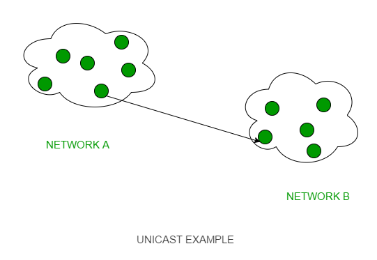
Characteristics include:
-
One-to-One Communication:
Unlike multicast (one-to-many) or broadcast (one-to-all), unicast routing focuses solely on delivering a packet from one sender to one specific receiver. -
Routing Table Entries:
In unicast routing, the routing tables are optimized to hold entries that help in precisely directing packets along the most efficient path to the individual destination. -
Protocols Involved:
Unicast routing uses various routing protocols (such as Distance Vector and Link State protocols) to build and update the routing tables that facilitate this one-to-one communication.
Protocols of Routing
1. Distance Vector Routing
https://www.geeksforgeeks.org/distance-vector-routing-dvr-protocol/
https://www.youtube.com/watch?v=5ZuP5qjbKSI&list=PLxCzCOWd7aiGFBD2-2joCpWOLUrDLvVV_&index=59 (must watch)
https://www.youtube.com/watch?v=UYASPR4jEkk&list=PLxCzCOWd7aiGFBD2-2joCpWOLUrDLvVV_&index=60 (Count to infinity problem in DVR)
Concept and Operation
-
Basic Idea:
In Distance Vector Routing, each router maintains a table (or "vector") that lists the distance (or cost) to reach every other router in the network and the direction (i.e., the next hop) to send packets. -
How It Works:
-
Periodic Updates:
Routers periodically share their routing tables with their immediate neighbors. -
Bellman-Ford Algorithm:
The algorithm used here is similar to the Bellman-Ford algorithm, where each router updates its table based on the information received from its neighbors. For each destination, a router selects the neighbor that offers the lowest cost (distance). -
Routing Table Convergence:
Over time, all routers converge on the best paths through iterative updates, so that each router eventually learns the shortest path to every destination.
-
Bellman-Ford Basics
(recapping from semester 4)
The Bellman-Ford Algorithm is the same as Dijkastra's algorithm, except that it works for negative edges which Dijkastra's cannot do so.
The Bellman-Ford Algorithm works by repeatedly relaxing the edges. Relaxation is the process of updating the shortest distance to each vertex by simply visiting it.
Step-by-Step Explanation
- Initialization: Start by setting the distance to source vertex as 0 and the distance to the rest of the vertices as infinity.
- Relaxation: For each edge, if the distance to the destination vertex can be shortened by taking the edge, updating the distance to the destination vertex.
- Check for negative cycles: After (V-1) iterations, V being the total number of vertices in the graph, check once more for any shorter paths available. If any more distances can be updated, this means there is a negative weight(or more) in the graph.
Example


Each router maintains a Distance Vector table containing the distance between itself and All possible destination nodes. Distances, based on a chosen metric, are computed using information from the neighbors’ distance vectors.
Information kept by DV router:
- Each router has an ID
- Associated with each link connected to a router,
    there is a link cost (static or dynamic).
- Intermediate hops


Distance Vector Table Initialization:

- Distance to itself = 0
- Distance to ALL other routers = infinity number.
covers these protocols extensively.
Metrics and Cost Calculation
-
Cost Metrics:
The "distance" can represent different metrics such as hop count, delay, bandwidth, or a composite metric. -
Example:
If Router A knows that the cost to Router B is 2 and Router B reports a cost of 3 to Router C, Router A will update its table to reflect a total cost of 2 + 3 = 5 to reach Router C, assuming that is the lowest available cost.
How Distance Vector Algorithm works?
- A router transmits its distance vector to each of its neighbors in a routing packet.
- Each router receives and saves the most recently received distance vector from each of its neighbors.
- A router recalculates its distance vector when:
- It receives a distance vector from a neighbor containing different information than before.
- It discovers that a link to a neighbor has gone down.
The DV calculation is based on minimizing the cost to each destination
Dx(y) = Estimate of least cost from x to y
C(x,v) =  Node x knows cost to each neighbor v
Dx   =  [Dx(y): y ? N ] = Node x maintains distance vector
Node x also maintains its neighbors' distance vectors
– For each neighbor v, x maintains Dv = [Dv(y): y ? N ]
Note:
- From time-to-time, each node sends its own distance vector estimate to neighbors.
- When a node x receives new DV estimate from any neighbor v, it saves v’s distance vector and it updates its own DV using B-F equation:
Dx(y) = min { C(x,v) + Dv(y), Dx(y) } for each node y ? N
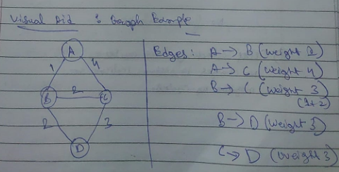
Example :
Consider 3-routers X, Y and Z as shown in figure. Each router have their routing table. Every routing table will contain distance to the destination nodes.
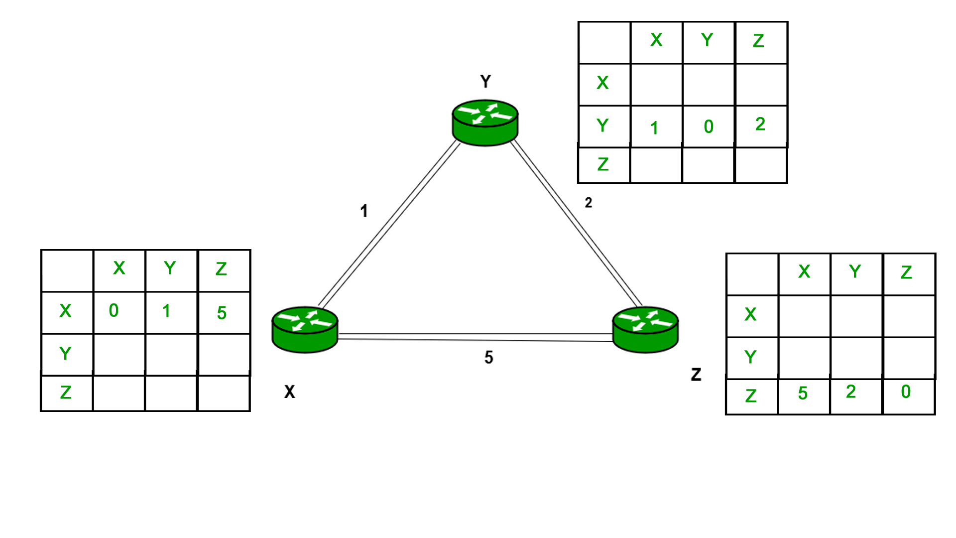
Consider router X , X will share it's routing table to neighbors and neighbors will share their routing tables to X and distance from node X to destination will be calculated using bellman-ford equation.
Dx(y) = min { C(x,v) + Dv(y)} for each node y ? N
As we can see that distance will be less going from X to Z when Y is intermediate node(hop) so it will be update in routing table X.
Similarly for Z also –
Finally the routing table for all –
Here's how this happened:
First X sent it's distance vector it's neighbor Y.
0 --> X
1 --> Y
5 --> Z
Now there's already a known path from X to Z of cost 5.
This is the case for both X --> Z and Z --> X.
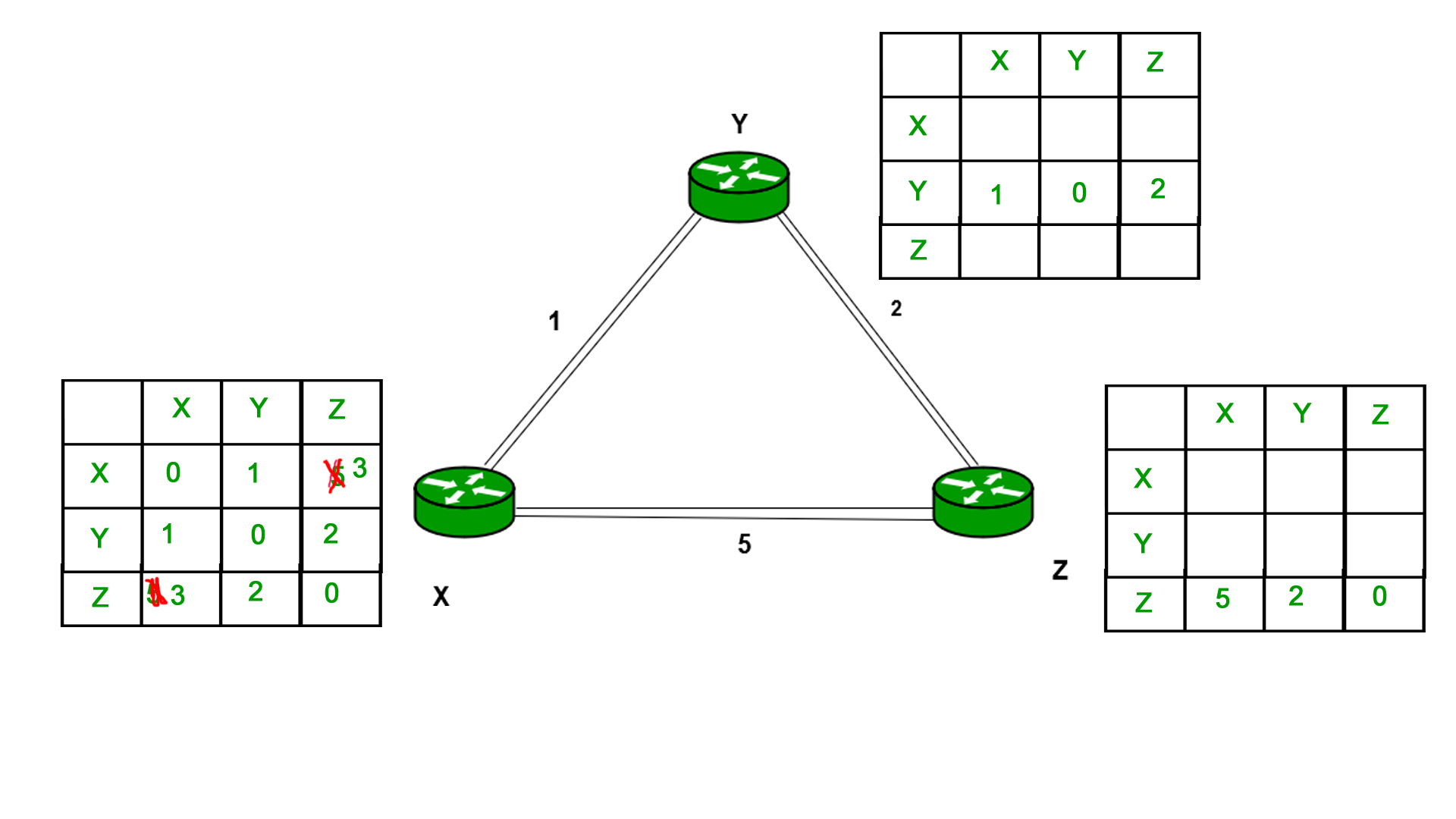
Once Y receives the distance vector of X, it updates it's own distance vector and sends to both X and Z
The distance vector is updated for Y as follows :
1 --> X
0 --> Y
2 --> Z
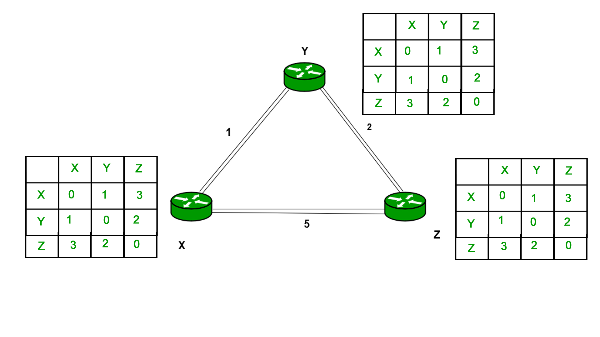
Now, when X and Z receive the distance vector from Y, their vectors are updated as follows.
For X :
0 --> X
1 --> Y
3 --> Z
For Z :
3 --> X
2 --> Y
0 --> Z
How did this updating take place? How did both X and Z decide to settle for the shorter path by hopping through Y?
Due to the B-F algorithm :
We take the minimum of the two distances.
So both X and Z had an initial path distance of 5.
And now after getting the distance vector from Y both X and Y see that a new distance is possible from X to Z and Z to X by hopping through Y which has a total cost of (1 + 2 = 3 or 2 + 1 = 3)
So they take the
Advantages
-
Simplicity:
The protocol is relatively simple to implement and understand. -
Low Overhead:
Routers exchange only their routing tables (or portions of them), which minimizes the information needed for routing decisions.
Disadvantages
-
Slow Convergence:
When network changes occur (such as link failures), the protocol may take longer to converge, leading to temporary routing loops or inconsistent routing information. -
Count-to-Infinity Problem:
In some scenarios, routers might repeatedly update their tables in a loop, gradually increasing the cost (or "counting to infinity") before converging to the correct value. Various techniques (like split horizon, route poisoning, and hold-down timers) are used to mitigate this issue.
Real-World Examples
- Routing Information Protocol (RIP):
RIP is a classic example of a distance vector protocol. It uses hop count as its metric (with a maximum of 15 hops), making it suitable for small to medium-sized networks.
2. Link State Routing
https://www.youtube.com/watch?v=kW6zV-040SY&list=PLxCzCOWd7aiGFBD2-2joCpWOLUrDLvVV_&index=61 (must watch)
Concept and Operation
-
Basic Idea:
In Link State Routing, each router has complete knowledge of the network's topology. Routers create a map (or "state") of the entire network and then compute the shortest path to every other node using an algorithm like Dijkstra’s. -
How It Works:
-
Link State Advertisements (LSAs):
Each router broadcasts information about its directly connected links (including the link cost) to all other routers in the network. These broadcasts are usually done using a flooding mechanism. -
Topology Database:
All routers collect these LSAs and build a common database that represents the network’s topology. -
Shortest Path Calculation:
Using the collected information, each router independently runs a shortest-path algorithm (commonly Dijkstra’s algorithm) to calculate the best path to every destination.
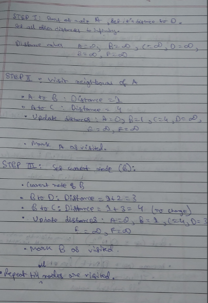
-
Calculation of Shortest Path
To find the shortest path, each node needs to run the famous Dijkstra algorithm.
Let's do a recap of Dijkastra's algorithm from semester 4.
Purpose: Dijkstra's algorithm is used to find the shortest path from a starting node (also called the source) to all other nodes in a weighted graph.
Step-by-Step Explanation:
-
Initialization:
- Start with a graph with nodes and weighted edges (weights represent the distance between nodes).
- Set the distance to the source node to 0 and all other nodes to infinity.
- Mark all nodes as unvisited and create a set of all the unvisited nodes.
-
Processing:
- While there are unvisited nodes:
- Select the unvisited node with the smallest distance (let's call this node u).
- For the current node u, consider all its unvisited neighbors. Calculate their tentative distances through u (i.e., the distance to u plus the distance from u to the neighbor).
- If the calculated tentative distance is less than the known distance, update the shortest distance to that neighbor.
- Mark the current node u as visited (it will not be checked again).
- While there are unvisited nodes:
-
Completion:
- The algorithm completes when all nodes have been visited. The shortest path to each node is now known.
Example
Let's take this graph
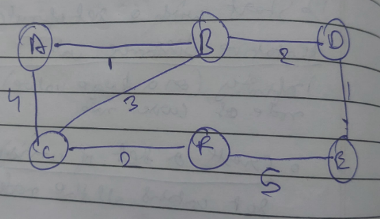

Or you can follow the example given in :
https://www.geeksforgeeks.org/unicast-routing-link-state-routing/
Advantages
-
Fast Convergence:
Since each router has complete and accurate topology information, link state protocols converge quickly after changes. -
Scalability and Flexibility:
They can handle larger, more complex network topologies and offer more granular control over routing decisions (e.g., by using more complex metrics). -
Loop-Free Paths:
The use of a global topology database and Dijkstra’s algorithm naturally avoids routing loops.
Disadvantages
-
Higher Overhead:
Flooding LSAs throughout the network and maintaining a complete topology database requires more memory and processing power. -
Complexity:
The protocol is more complex to implement and manage compared to distance vector routing.
Real-World Examples
-
Open Shortest Path First (OSPF):
OSPF is one of the most common link state routing protocols used in large enterprise networks. -
Intermediate System to Intermediate System (IS-IS):
IS-IS is another link state protocol widely used in service provider networks.