Module 4 -- Transport Layer -- Computer Networks
Index
- Transport Layer
- Protocols of the Transport Layer
- 1. User Datagram Protocol (UDP)
- 2. Transmission Control Protocol (TCP)
- Three-Way Handshake in TCP
- TCP Connection Termination
- TCP Congestion Control
- QoS (Quality of Service) Implementations
- 1. Leaky Bucket Algorithm
- 2. Token Bucket Algorithm
Transport Layer
https://www.geeksforgeeks.org/transport-layer-responsibilities/
https://www.youtube.com/watch?v=kAty4mKczEg&list=PLxCzCOWd7aiGFBD2-2joCpWOLUrDLvVV_&index=64
The Transport Layer, which is the 4th layer in the OSI model, acts as the interface between the application and network layers. Its main job is to ensure that data sent by an application on one host is delivered reliably, in order, and to the correct process on another host.
While Data Link Layer requires the MAC address (48 bits address contained inside the Network Interface Card of every host machine) of source-destination hosts to correctly deliver a frame and the Network layer requires the IP address for appropriate routing of packets, in a similar way Transport Layer requires a Port number to correctly deliver the segments of data to the correct process amongst the multiple processes running on a particular host. A port number is a 16-bit address used to identify any client-server program uniquely.
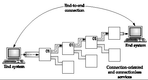
1. End-to-End (Port-to-Port) Delivery
-
Purpose:
The primary function of the Transport Layer is to provide end-to-end delivery, which is sometimes referred to as port-to-port or process-to-process delivery. This means that the data is delivered from a specific application (or process) on the source machine to the corresponding application on the destination machine. -
Use of Port Numbers:
-
Logical Identification:
Every application that sends or receives data uses a unique port number (a 16-bit number). -
Well-Known and Registered Ports:
Some port numbers are standardized (e.g., SMTP uses port 25) so that applications know where to send or listen for data. -
Example Scenario:
If a user sends an email, the sending application attaches the source port (say, 25 for SMTP) and the destination port (assigned to the email server on the receiver’s side). This ensures that only the intended application processes the data.
-
2. Protocols: TCP and UDP
-
Transmission Control Protocol (TCP):
-
Connection-Oriented:
TCP establishes a connection between the sender and receiver (much like making a phone call) before data is transmitted. -
Reliability and In-Order Delivery:
TCP ensures that all packets reach their destination, in the correct order, and without loss. If packets are missing or out of order, TCP detects and corrects these issues using acknowledgments, sequence numbers, and retransmissions. -
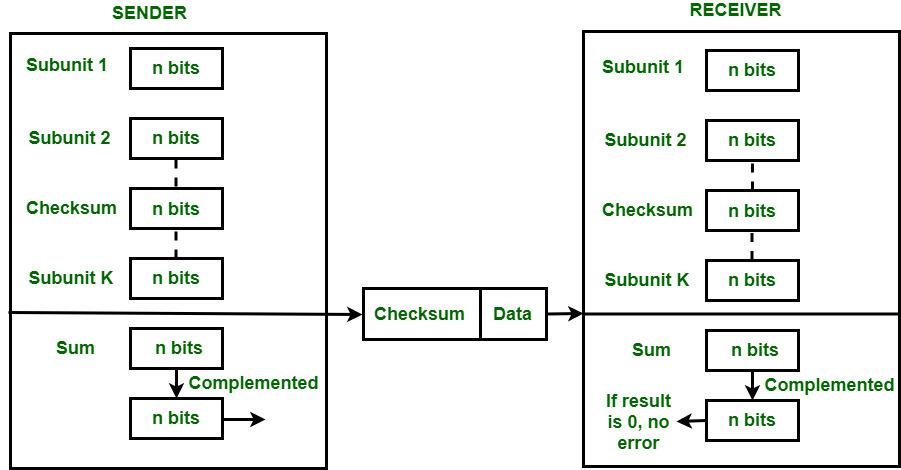
Error Control:
TCP uses checksums to detect errors. The receiver calculates the checksum of the incoming data and compares it with the one sent by the sender. If they don’t match, the packet is assumed to be corrupted.
-
-
User Datagram Protocol (UDP):
-
Connectionless:
UDP does not establish a connection before sending data; it simply sends packets without ensuring that they reach the destination. -
No Reliability Mechanisms:
There is no guarantee of in-order delivery or error checking beyond a basic checksum. UDP is suitable for applications where speed is more critical than reliability (e.g., live streaming or online gaming).
-
3. Segmentation
-
Continuous Data Stream:
Data from the application layer often comes as a continuous stream. -
Breaking Down Data:
The Transport Layer segments this continuous stream into smaller, manageable pieces called segments. -
Segment Structure:
Each segment includes a header (with information such as source/destination port numbers, sequence numbers, and error-checking data) and a data portion. -
Purpose:
Segmentation makes it easier for the Network Layer to handle the data and for the receiver to reassemble the segments in the correct order.
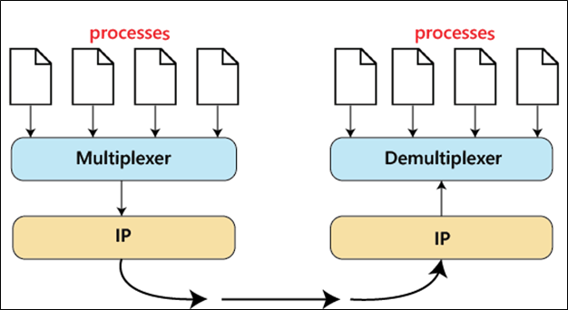
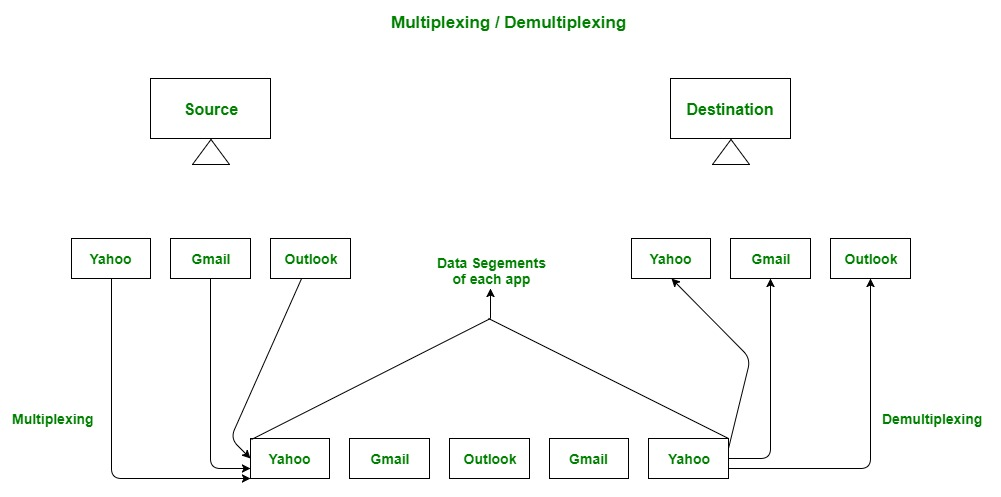
4. Multiplexing and Demultiplexing
-
Multiplexing:
-
Definition:
When multiple applications on a host send data simultaneously, the Transport Layer combines (multiplexes) these streams into a single flow that is passed to the Network Layer. -
Benefit:
This efficient sharing of the network connection ensures that data from different applications can be transmitted over the same physical link.
-
-
Demultiplexing:
-
Definition:
At the destination, the Transport Layer separates (demultiplexes) the received data and delivers each segment to the appropriate application based on the port number. -
Result:
Each application receives only the data intended for it.
-
5. Flow Control and Congestion Control
-
Flow Control:
-
Purpose:
Flow control prevents the sender from overwhelming the receiver by sending data too fast. -
Mechanism:
The receiver advertises a “window size,” which indicates the amount of data it can buffer at a time. The sender adjusts its transmission rate accordingly.
-
-
Congestion Control:
-
Objective:
Congestion control manages the overall network traffic to avoid overwhelming the network, which can lead to packet loss and delays. -
Techniques:
Algorithms like AIMD (Additive Increase Multiplicative Decrease) help adjust the rate at which data is sent based on current network conditions.Leaky bucket technique
Token Ring technique -
Interaction with Flow Control:
While flow control is concerned with the sender and receiver, congestion control is about the state of the network as a whole.
-
6. Error Control
-
Error Detection:
The Transport Layer uses checksums to detect errors in the data segments. -
Error Recovery:
In TCP, if an error is detected (for example, a mismatch in the checksum), the affected segments can be retransmitted to ensure complete and correct data delivery. -
Importance:
This error control is crucial for maintaining data integrity, especially in applications where even small errors can lead to significant problems (e.g., file transfers).
7. Overall Summary
-
End-to-End Delivery:
The Transport Layer guarantees that data is delivered from a specific process on the source machine to a specific process on the destination machine by using port numbers. -
Protocol Choice:
TCP provides reliable, in-order delivery with error control, flow control, and congestion management. UDP offers a faster, but less reliable, connectionless alternative. -
Segmentation & Multiplexing:
It breaks down large streams of data into segments, then multiplexes data from various applications for transmission and later demultiplexes them at the receiver’s end. -
Control Mechanisms:
Flow control and congestion control ensure efficient and fair use of network resources, preventing overload and maintaining performance.
Protocols of the Transport Layer
1. User Datagram Protocol (UDP)
https://www.youtube.com/watch?v=HF_znV8x9a0&list=PLxCzCOWd7aiGFBD2-2joCpWOLUrDLvVV_&index=72
https://www.geeksforgeeks.org/user-datagram-protocol-udp/
User Datagram Protocol (UDP) is a Transport Layer protocol. UDP is a part of the Internet Protocol suite, referred to as UDP/IP suite. Unlike TCP, it is an unreliable and connectionless protocol. So, there is no need to establish a connection before data transfer. The UDP helps to establish low-latency and loss-tolerating connections over the network. The UDP enables process-to-process communication.
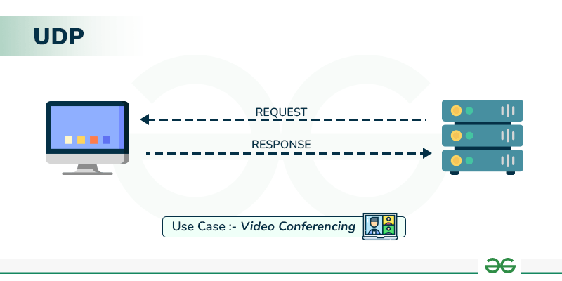
1. Connectionless Nature
-
No Connection Establishment:
Unlike TCP, UDP does not set up a connection before data transfer. There’s no handshake (no “dial tone” or “connection setup”)—data is simply sent as independent packets, much like dropping a letter in a mailbox. -
Analogy:
Think of UDP like postal mail: you put your letter in an envelope (with the necessary addressing) and drop it in the post without waiting for any connection or acknowledgment that the recipient is ready. -
Implications:
-
Unreliable: There’s no guarantee that a packet will arrive at its destination.
-
No In-Order Delivery: Packets might arrive out of order since they travel independently and may take different routes.
-
No Retransmission: Lost or corrupted packets are not automatically resent.
-
2. UDP Header Structure
The UDP header is very simple and consists of only four fields, each 16 bits in size:
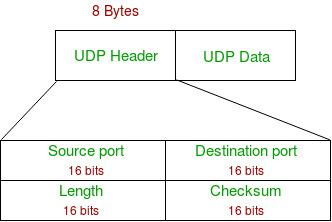
a. Source Port
-
Purpose:
Indicates the port number of the sending application. -
Range:
Port numbers range from 0 to 65535. Ports 0–1023 are well-known ports, while the rest are used for other purposes or dynamically assigned by the operating system.
b. Destination Port
- Purpose:
Specifies the port number of the receiving application. This ensures that the data is delivered to the correct process on the destination machine.
c. Length
-
Purpose:
This field indicates the total length of the UDP datagram, which includes both the header (always 8 bytes) and the payload (the actual data). -
Maximum Size:
The maximum value for a 16-bit field is 65535 bytes. Since the header occupies 8 bytes, the maximum payload size is 65,535 − 8 = 65,527 bytes.
d. Checksum
-
Purpose:
The checksum is used for error detection. It is calculated over the UDP header, the payload, and a pseudo-header from the IP layer. The pseudo-header includes parts of the IP header (like source and destination IP addresses) that remain constant during transmission. -
Optional in IPv4, Mandatory in IPv6:
-
In IPv4, the checksum field is optional—if not used, it can be set to zero.
-
In IPv6, the checksum is mandatory, ensuring that errors in the UDP segment can be detected.
-
3. Key Characteristics of UDP
-
Speed and Efficiency:
Since UDP is connectionless and has minimal overhead (only an 8-byte header), it’s faster and uses less bandwidth compared to TCP. This makes UDP suitable for real-time applications like live video streaming, online gaming, or VoIP, where speed is crucial and occasional packet loss is acceptable. -
Unreliability:
UDP does not guarantee delivery. Packets may be lost, duplicated, or received out of order. Applications that use UDP must either handle these issues at the application layer or be tolerant of them. -
No Built-In Flow or Congestion Control:
Unlike TCP, UDP does not manage data flow or congestion control. It simply sends packets without considering network congestion, so it’s up to the application or higher layers to manage these aspects if needed. -
No Acknowledgments or Retransmissions:
UDP does not provide acknowledgments or automatic retransmissions for lost packets, which contributes to its low overhead but also its unreliability.
4. Use Cases for UDP
Because of its characteristics, UDP is commonly used in scenarios where low latency is more important than reliability, and where the application can tolerate some data loss:
-
Streaming Media: Video and audio streaming where a slight loss of data might only cause minor glitches.
-
Online Gaming: Fast-paced games where timely delivery is more important than perfect accuracy.
-
VoIP (Voice over IP): Real-time voice communication where delays are unacceptable.
-
DNS (Domain Name System): Query responses that are designed to be fast and lightweight.
2. Transmission Control Protocol (TCP)
https://www.youtube.com/watch?v=c8aet11HNxg&list=PLxCzCOWd7aiGFBD2-2joCpWOLUrDLvVV_&index=66 (Part 1)
https://www.youtube.com/watch?v=hsNuqtfxgRI&list=PLxCzCOWd7aiGFBD2-2joCpWOLUrDLvVV_&index=67 (Part 2)
https://www.geeksforgeeks.org/what-is-transmission-control-protocol-tcp/
TCP, or Transmission Control Protocol, is a cornerstone protocol at the Transport Layer that provides reliable, ordered, and error-checked delivery of data between applications. Unlike UDP, TCP is connection-oriented and builds a reliable channel between two endpoints.
1. Core Features of TCP
a. Connection-Oriented Communication
-
Three-Way Handshake:
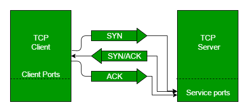
TCP establishes a connection before any data is transmitted. This is done through a three-way handshake: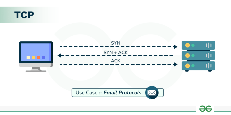
-
SYN: The client sends a segment with the SYN flag to initiate a connection.
-
SYN-ACK: The server responds with a segment that has both the SYN and ACK flags set.
-
ACK: The client sends an ACK to complete the connection setup.
-
-
Reliability:
Once the connection is established, TCP ensures that all segments arrive at the destination. If any segments are lost or corrupted, they are retransmitted.
b. Byte Streaming and Segmentation
-
Byte Streaming:
TCP treats data as a continuous stream of bytes. There is no inherent message boundary at the transport layer; it is the responsibility of the application to impose structure if needed. -
Segmentation:
The continuous stream is divided into segments. Each segment is a collection of bytes and includes a TCP header with control information to manage data transfer.
c. Full-Duplex Communication
- Simultaneous Data Flow:
TCP supports full duplex, meaning that both ends of the connection can send and receive data concurrently. This is essential for interactive applications.
d. Reliable Data Transfer and Error Control
-
Sequence and Acknowledgement Numbers:
-
Sequence Number: Every byte in the TCP stream is numbered. This helps in reassembling the segments in the correct order at the receiver.
-
Acknowledgement Number: The receiver sends an acknowledgement number indicating the next expected byte, confirming the receipt of previous data.
-
-
Error Detection:
A checksum is calculated over the header, data, and a pseudo-header from the IP layer. This checksum helps the receiver detect errors in the segment. If the checksum does not match, the segment is discarded and later retransmitted.
e. Flow Control and Congestion Control
-
Flow Control:
TCP uses a sliding window mechanism to manage the rate at which data is sent. The receiver advertises a window size, which is the amount of data it can buffer. This prevents the sender from overwhelming the receiver. -
Congestion Control:
TCP implements algorithms (such as AIMD—Additive Increase Multiplicative Decrease) to adjust the data transmission rate based on current network congestion. This ensures that the network does not become overloaded, reducing packet loss and improving overall performance.
f. Piggybacking
- Combining Acknowledgements with Data:
When possible, TCP combines (or "piggybacks") acknowledgement information with outgoing data segments, reducing overhead and improving efficiency.
2. Overview of the TCP Header
TCP adds a header to every segment. The header contains various fields that control the behavior of the protocol:
a. Source and Destination Ports (16 bits each)
- Purpose:
Identify the sending and receiving applications. Port numbers range from 0 to 65,535, with well-known ports (0–1023) reserved for standard services (e.g., HTTP uses port 80).
b. Sequence Number (32 bits)
- Usage:
Indicates the position of the first byte of data in the segment within the overall byte stream. This enables the receiver to reassemble segments in the proper order.
c. Acknowledgement Number (32 bits)
- Usage:
When the ACK flag is set, this number represents the next byte expected by the receiver, acknowledging receipt of all prior bytes.
d. Data Offset (Header Length) (4 bits)
- Purpose:
Specifies the length of the TCP header in 32-bit words. The minimum header size is 20 bytes (5 words). This field tells the receiver where the data begins. Multiplying the value by 4 gives the header length in bytes.
e. Reserved Bits (6 bits)
- Purpose:
Reserved for future use and set to zero.
f. Control Flags (6 bits)
-
Flags include:
-
URG: Urgent pointer field is valid.
-
ACK: Acknowledgement field is valid.
-
PSH: Push function; instructs to push data to the application immediately.
-
RST: Reset the connection.
-
SYN: Synchronize sequence numbers to initiate a connection.
-
FIN: No more data from the sender; used to terminate the connection.
These flags allow TCP to manage connection setup, data transfer, and termination.
-
g. Window Size (16 bits)
- Usage:
Indicates the size of the receiver’s buffer (in bytes), which informs the sender of how much data can be sent before waiting for an acknowledgement. This is a key element of TCP’s flow control mechanism.
h. Checksum (16 bits)
- Purpose:
Provides error-checking for the header, data, and a pseudo-header (which includes select fields from the IP header, such as source and destination IP addresses). If the checksum computed by the receiver does not match the one in the header, the segment is assumed to be corrupted.
i. Urgent Pointer (16 bits)
- Usage:
If the URG flag is set, this field indicates the end of the urgent data. It helps the receiving system process urgent data immediately.
j. Options and Padding (Variable)
-
Options:
Provide additional functionality. One common option is the Maximum Segment Size (MSS), which tells the sender the largest segment size that can be handled by the receiver. -
Padding:
Added to ensure the TCP header is a multiple of 32 bits.
3. Summary of TCP Functionality
-
Connection Establishment and Teardown:
TCP’s three-way handshake and connection termination procedures ensure a reliable, ordered session. -
Reliable, In-Order Delivery:
Through sequence numbers, acknowledgements, and retransmission mechanisms, TCP guarantees that data arrives intact and in the proper order. -
Flow and Congestion Control:
These mechanisms allow TCP to adjust the rate of data transfer based on network and receiver conditions, preventing congestion and avoiding overwhelming the receiver. -
Segmenting and Multiplexing:
TCP segments the continuous byte stream from the application layer into manageable pieces, while multiplexing allows multiple applications to share a single network connection. -
Error Control:
Using checksums and retransmission strategies, TCP detects and recovers from data corruption.
Three-Way Handshake in TCP
https://www.youtube.com/watch?v=qIEHUUt2Wfc&list=PLxCzCOWd7aiGFBD2-2joCpWOLUrDLvVV_&index=68
https://www.geeksforgeeks.org/tcp-3-way-handshake-process/
The TCP three-way handshake is the process used to establish a reliable connection between two endpoints before any actual data is transmitted. This handshake ensures that both the client and server are ready to communicate, agree on initial sequence numbers, and set up necessary parameters like window size and maximum segment size (MSS). Here’s a detailed explanation of the process:
1. Purpose of the Three-Way Handshake
-
Connection Establishment:
Before data can be exchanged, TCP must create a logical connection between the two endpoints. This setup reserves system resources (like buffer space and CPU time) on both sides. -
Reliability:
By establishing the connection first, TCP ensures that both parties are aware of the connection and that data will be delivered reliably. It also allows both sides to synchronize their sequence numbers and agree on flow control parameters. -
Full Duplex Operation:
Once established, the connection is full duplex, meaning both the client and server can send data simultaneously.
2. Steps of the Three-Way Handshake
Step 1: SYN (Synchronize) — Active Open
-
Client Initiates Connection:
-
Action: The client (let’s call it A) sends a segment with the SYN flag set.
-
Key Fields in the SYN Packet:
-
Source Port & Destination Port: Identify the client’s and server’s applications.
-
Sequence Number: A randomly chosen initial sequence number (e.g., 9000) is used. This number isn’t zero to avoid conflicts if multiple connections start simultaneously.
-
SYN Flag: Set to 1 to indicate a connection request.
-
Window Size: The client advertises its buffer capacity (e.g., 12000 bytes), which tells the server how much data it can accept.
-
Options: Often includes parameters like the Maximum Segment Size (MSS), which tells the server the largest segment it can send (e.g., 1200 bytes).
-
-
-
Analogy:
Think of this as the client “dialing” the server’s number, indicating that it wants to start a conversation and is ready to send data.
Step 2: SYN-ACK (Synchronize-Acknowledge) — Passive Open
-
Server Responds:
-
Action: The server (B), which is passively waiting for incoming connection requests, receives the SYN packet and replies with a segment that has both the SYN and ACK flags set.
-
Key Fields in the SYN-ACK Packet:
-
Source Port & Destination Port: These are the reverse of what the client used.
-
Sequence Number: The server selects its own random initial sequence number (e.g., 3000).
-
Acknowledgement Number: Set to the client’s initial sequence number plus 1 (e.g., 9001), indicating that the server has received the client’s SYN.
-
SYN Flag: Set to 1 to continue the connection setup.
-
ACK Flag: Set to 1 to acknowledge the client’s SYN.
-
Window Size: The server advertises its own receiving capacity (e.g., 18000 bytes).
-
Options: May include its own MSS value (e.g., 600 bytes), which informs the client about the maximum segment size the server can handle.
-
-
-
Analogy:
The server’s SYN-ACK is like answering a phone call and confirming that it is ready to talk while sharing its own connection parameters.
Step 3: ACK (Acknowledge) — Active Confirmation
-
Client Acknowledges Server’s Response:
-
Action: The client receives the SYN-ACK and sends a final ACK segment.
-
Key Fields in the ACK Packet:
-
Acknowledgement Number: Set to the server’s sequence number plus 1 (e.g., if the server’s sequence was 3000, the client sends 3001). This tells the server that the client has received its SYN-ACK.
-
Sequence Number: Continues from the client’s previous sequence number (remains at 9001 if no data is sent yet).
-
ACK Flag: Set to 1, confirming receipt of the server’s message.
-
-
-
Outcome:
Once this ACK is sent, the handshake is complete, and a full-duplex connection is established. Now, both endpoints know where to begin the actual data transmission, and both are synchronized in terms of sequence numbers and flow control parameters.
3. Key Concepts Illustrated in the Handshake
-
Sequence Numbers:
Randomly generated numbers ensure that both endpoints start with a unique identifier. They are crucial for ordering the bytes in the stream and for detecting duplicates or lost segments. -
Acknowledgement Numbers:
By acknowledging the receipt of a SYN with an incremented sequence number, both sides confirm that they are synchronized and ready for data transfer. -
Window Size and MSS Options:
These fields help with flow control (how much data can be sent before needing an acknowledgement) and ensure that the segments are sized appropriately according to the network’s capabilities. -
Full Duplex and Reliability:
The handshake ensures that both the client and server can communicate simultaneously and reliably, as both have agreed on the initial parameters and are now ready to exchange data.
4. Summary
-
Connection Establishment:
TCP’s three-way handshake sets up a connection by exchanging SYN, SYN-ACK, and ACK packets, establishing initial sequence numbers and connection parameters. -
Resource Reservation:
During the handshake, each endpoint advertises its capacity (window size) and parameters (MSS), ensuring that both sides are ready for reliable, full-duplex communication. -
Reliability and Synchronization:
This process guarantees that both the client and server are synchronized with respect to sequence numbers, which is fundamental for ensuring reliable and in-order data delivery throughout the session.
Piggybacking and Pure Acknowledgement in TCP
https://www.youtube.com/watch?v=7zPfuIf4GL0&list=PLxCzCOWd7aiGFBD2-2joCpWOLUrDLvVV_&index=69
TCP supports two methods for conveying acknowledgements during data transfer:
1. Piggybacking
Definition:
-
Piggybacking means that when a TCP segment is sent, it can carry both data and an acknowledgement for the data that has been received from the other side.
-
In other words, rather than sending a separate segment just to acknowledge receipt, the acknowledgement is “piggybacked” onto a data segment.
How It Works:
-
Bidirectional Data Flow:
TCP is full duplex, meaning both sides can send data simultaneously. For example, if a client is sending data to a server and at the same time the server has data to send, the server can include an acknowledgement for the client’s data along with its own outbound data. -
Efficiency Benefits:
-
Combining data and acknowledgements in a single segment reduces the number of packets on the network.
-
This decreases overhead and minimizes network congestion, as fewer packets are sent overall.
-
-
Example Scenario:
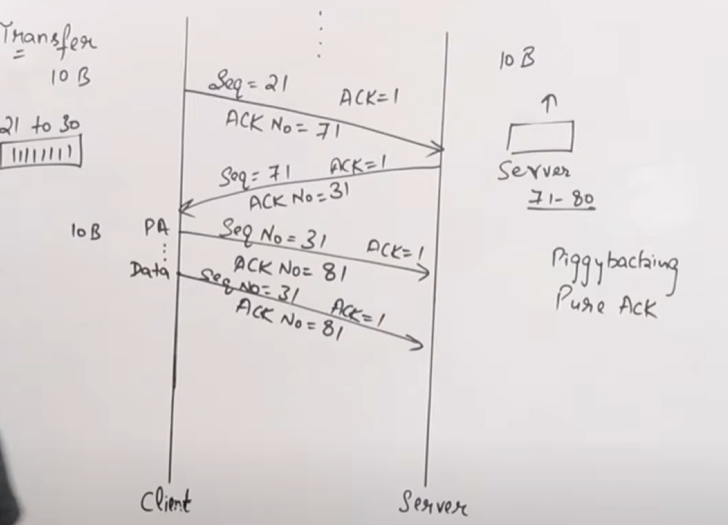
Suppose the client sends a segment containing bytes 21–30. When the server receives this segment, it prepares a response that includes its own data (say, bytes 71–80) and, in the same segment header, sets the acknowledgement number to 31 (indicating it has received all data up to byte 30). This single segment both delivers data and confirms receipt, saving the extra packet that would have been used solely for acknowledgement.
2. Pure Acknowledgement
Definition:
- A pure acknowledgement is a TCP segment sent solely for the purpose of acknowledging received data, with no actual data payload attached.
How It Works:
-
When It’s Used:
-
There are occasions when a TCP endpoint has no new data to send but still needs to confirm that it has received data from the other side.
-
For example, if the server receives data from the client and, at that moment, has no outgoing data to piggyback an acknowledgement on, it will send a pure acknowledgement.
-
-
Segment Contents:
-
The segment contains only the TCP header with the ACK flag set and the acknowledgement number indicating the next expected byte.
-
Since there is no data payload, the sequence number in such a segment is not advanced.
-
-
Example Scenario:
Consider the client sends a segment with bytes numbered 21–30. If the server does not have any data to send back immediately, it might simply reply with a pure acknowledgement segment setting the acknowledgement number to 31. This informs the client that its segment was received without adding any extra data, ensuring that the sender can continue sending subsequent segments.
3. Why Both Methods Are Important
-
Reducing Overhead:
Piggybacking minimizes the number of separate packets on the network, leading to better efficiency and lower congestion. -
Ensuring Timely Feedback:
Pure acknowledgements ensure that even if no data is ready to be sent in the reverse direction, the sender still receives confirmation of successful receipt. This prevents timeouts and helps maintain the reliability of the connection. -
Flow and Congestion Control:
Both mechanisms contribute to TCP’s flow control strategy. By acknowledging received segments, the sender knows how much data the receiver is ready for, while piggybacking helps in reducing the load on the network by combining operations.
4. Summary
-
Piggybacking:
Combines data transmission and acknowledgements in one segment, which is efficient and reduces network traffic. -
Pure Acknowledgement:
Is used when there’s no data to send, ensuring that the sender is informed of successful receipt through an acknowledgment-only segment.
TCP Connection Termination
https://www.youtube.com/watch?v=dJIAComFq9U&list=PLxCzCOWd7aiGFBD2-2joCpWOLUrDLvVV_&index=70
TCP connection termination is the process by which a TCP session is gracefully closed once no further data is to be exchanged. Unlike connection establishment—which uses a three-way handshake—termination can occur in either a three-step or a four-step process depending on whether one side immediately closes its half of the connection or delays it to send remaining data.
1. Key Concepts
-
Graceful Shutdown vs. Abrupt Closure:
TCP is designed to release resources in an orderly fashion. Both sides (client and server) must agree that they are done sending data, ensuring that all transmitted data is acknowledged. -
Half-Close:
Terminating one direction of data flow while the other may still be active is known as a half-close. When one side sends a FIN, it stops sending further data but can still receive data until it, too, sends a FIN. -
Sequence Number Consumption:
FIN packets consume one sequence number. Acknowledgement-only segments, however, do not consume sequence numbers.
2. The Termination Process
Scenario 1: Three-Step (Three-Way) Termination
This is the most common scenario when both sides are ready to close the connection simultaneously:
-
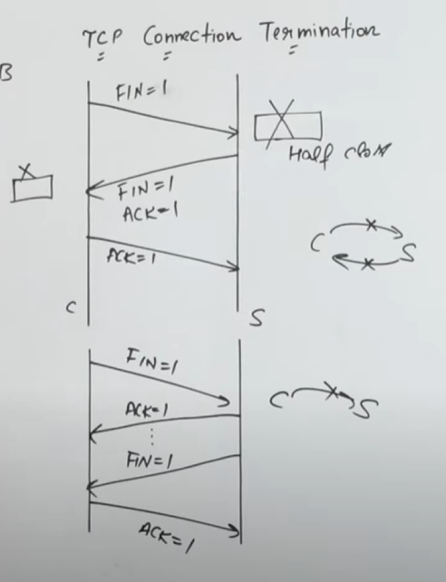
FIN from the Initiator (Client):
-
Action: The client sends a FIN packet to the server.
-
Meaning: The client indicates that it has no more data to send.
-
Sequence Impact: This FIN consumes one sequence number.
-
-
FIN+ACK from the Peer (Server):
-
Action: Upon receiving the FIN, the server releases its resources (for the client-to-server direction) and sends back a combined FIN and ACK packet.
-
ACK Component: This acknowledges the client’s FIN (for example, if the client’s FIN used sequence number X, the server’s ACK number will be X+1).
-
FIN Component: Simultaneously, the server indicates that it, too, is ready to terminate its side of the connection by setting the FIN flag.
-
Sequence Impact: The server’s FIN consumes one sequence number from its own sequence space.
-
-
Final ACK from the Initiator (Client):
-
Action: The client sends an ACK packet acknowledging the server’s FIN (e.g., if the server’s FIN used sequence number Y, the client sends an ACK number Y+1).
-
Note: This final ACK is sent solely for acknowledgment and does not consume a sequence number.
-
Result: After this ACK, both sides have agreed that no more data will be sent, and the connection is terminated.
-
Scenario 2: Four-Step Termination
In some cases, one side (say, the server) may have additional data to send even after receiving a FIN, leading to a delayed termination:
-
FIN from the Initiator (Client):
- The client sends a FIN to indicate it has finished sending data.
-
Pure ACK from the Peer (Server):
-
Instead of immediately sending its own FIN, the server sends a pure ACK for the client’s FIN, confirming that it has received the termination request.
-
Implication: The connection is half-closed; the client cannot send further data, but the server can continue to transmit any remaining data.
-
-
Server Sends Data (if needed):
- The server may now continue to send remaining data or control messages. During this period, the server’s connection remains open for sending data even though it has acknowledged the client’s FIN.
-
Server Sends FIN (and possibly FIN+ACK):
-
When the server has finished sending its data, it sends a FIN packet (or a FIN+ACK packet) to indicate that it too is done.
-
The client then responds with a final ACK, just as in the three-step process.
-
3. Important Points to Remember
-
Resource Release:
When one side sends a FIN, it releases the resources (like buffers) reserved for sending data in that direction. However, it can still receive data until it completes the termination process. -
Sequence Number Consumption:
The FIN flag uses up one sequence number in the sender’s sequence space. The final ACK does not consume any new sequence number—it’s simply acknowledging receipt. -
Acknowledgement Role:
Every FIN must be acknowledged. In the pure ACK phase, even if no new data is sent, acknowledgements ensure both sides know that their termination request has been received. -
Full Duplex Closure:
Because TCP is full duplex, termination must occur for both directions. This can be done simultaneously (3-step) or sequentially (4-step) depending on whether one side has more data to send.
4. Visualizing the Process
Imagine two people (client and server) on a phone call:
-
Client: “I’m done talking (FIN).”
-
Server: “I got it. I’m done too (FIN+ACK)” or “I got it (pure ACK), but I have one more thing to say… then I’ll say I’m done (later FIN).”
-
Client: “Okay, I acknowledge that you’re done (final ACK).”
TCP Congestion Control
TCP congestion control is a set of algorithms designed to prevent network congestion and ensure efficient data transmission. Its primary goal is to adapt the rate of data transmission based on the network’s capacity, thereby avoiding packet loss due to overload.
1. Why Congestion Control?
-
Network Overload:
When too many packets are sent too quickly, intermediate routers can become overwhelmed, leading to packet loss and increased latency. -
Dynamic Network Conditions:
The available bandwidth on a network can change rapidly. TCP congestion control helps adjust the sender’s transmission rate in real time.
2. Key Components of TCP Congestion Control
a. Congestion Window (cwnd)
-
Definition:
A dynamic window maintained by the sender that limits the amount of unacknowledged data in the network. -
Purpose:
The size of cwnd controls how many bytes can be sent before waiting for acknowledgements (ACKs). It is adjusted based on network feedback.
b. Slow Start
-
Initial Phase:
-
TCP begins transmission with a small cwnd (often one or a few segments) to probe the network capacity.
-
Exponential Growth:
For every ACK received, the cwnd increases exponentially (roughly doubling each round-trip time) until a threshold is reached.
-
-
Objective:
Quickly find an approximate level of network capacity without causing immediate congestion.
c. Congestion Avoidance
-
Transition Phase:
-
Once cwnd reaches a threshold (ssthresh), TCP switches from exponential growth to a linear increase.
-
Additive Increase:
The cwnd increases gradually (typically by one segment per round-trip time).
-
-
Purpose:
To cautiously probe for additional available bandwidth without overwhelming the network.
d. Multiplicative Decrease
-
Reaction to Congestion:
-
When packet loss is detected (usually inferred from a timeout or the receipt of duplicate ACKs), TCP assumes the network is congested.
-
Decrease cwnd:
The congestion window is reduced multiplicatively (often halved) to quickly lower the sending rate.
-
-
Objective:
To relieve congestion by drastically reducing the load on the network.
e. Fast Retransmit and Fast Recovery
-
Fast Retransmit:
- If the sender receives a certain number of duplicate ACKs (typically three), it assumes that a packet was lost and retransmits that packet immediately, rather than waiting for a timeout.
-
Fast Recovery:
-
After fast retransmit, rather than reverting to slow start, TCP enters fast recovery.
-
Adjustment:
The cwnd is reduced (multiplicative decrease) but then increased gradually to continue transmission without completely restarting the connection.
-
-
Goal:
To recover from minor losses without drastically lowering the transmission rate.
3. How These Algorithms Work Together
-
Start and Probe:
TCP begins with slow start to quickly ramp up the transmission rate. This phase continues until the network shows signs of congestion. -
Avoid Overload:
Once nearing the network capacity, TCP shifts to congestion avoidance, increasing the window size linearly to carefully use the available bandwidth. -
React to Loss:
When packet loss is detected, TCP performs a multiplicative decrease to reduce the congestion window, thereby reducing the load on the network. -
Quick Recovery:
If packet loss is minor (detected via duplicate ACKs), fast retransmit and fast recovery allow TCP to retransmit the missing segment and continue data transmission without going all the way back to slow start. -
Continuous Adjustment:
This cycle of slow start, congestion avoidance, and multiplicative decrease continues throughout the lifetime of the connection, allowing TCP to adapt dynamically to changing network conditions.
4. Impact on Network Efficiency
-
Fairness:
TCP’s congestion control mechanisms help multiple TCP connections share the available network bandwidth fairly. -
Throughput vs. Stability:
While the algorithms aim to maximize throughput, they also prioritize network stability by preventing congestion collapse—a state where too many retransmissions and delays drastically reduce overall network performance.
5. Summary
TCP congestion control is essential for maintaining efficient, stable network communications. It does this by:
-
Starting with a conservative sending rate (slow start) and then gradually increasing it (congestion avoidance).
-
Reacting swiftly to congestion signals by reducing the sending rate (multiplicative decrease).
-
Using mechanisms like fast retransmit and fast recovery to handle minor packet losses without a full restart.
QoS (Quality of Service) Implementations
1. Leaky Bucket Algorithm
https://www.geeksforgeeks.org/leaky-bucket-algorithm/
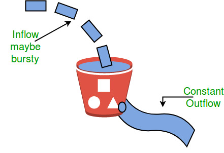
Concept Overview
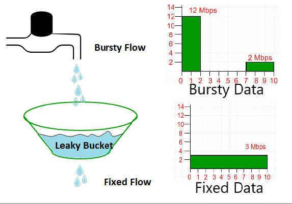
- Analogy:
Imagine a bucket with a small hole at the bottom. Water (data packets) enters the bucket at varying rates, but the water leaks out at a constant rate. If water flows in too quickly and the bucket overflows, the excess water is discarded.
How It Works
-
Queueing and Emission:
Incoming packets are placed in a queue (the bucket). They exit (are transmitted) at a fixed, predetermined rate regardless of bursts in incoming traffic. -
Constant Outflow:
The outflow is regulated to be steady. Even if a burst of packets arrives, they are released into the network at the fixed rate. -
Overflow Handling:
If the incoming packet rate exceeds the bucket's capacity (i.e., the bucket overflows), the extra packets are dropped. This mechanism enforces a strict output rate and limits bursts.
Key Points
-
Traffic Shaping:
The leaky bucket smooths out bursts in traffic, ensuring a constant output rate. -
Dropping Packets:
Excess traffic that the bucket cannot hold is discarded, which helps prevent network congestion. -
Simplicity:
It is simple to implement and provides a clear mechanism to enforce rate limits.
2. Token Bucket Algorithm
Concept Overview
- Analogy:
Imagine a bucket that holds tokens, which are added at a constant rate. To send a packet, the system must remove tokens from the bucket. Each packet requires a specific number of tokens based on its size. If there aren’t enough tokens, the packet must wait until more tokens accumulate.
How It Works
-
Token Generation:
Tokens are generated at a steady rate and accumulate in a bucket up to a maximum capacity. -
Packet Transmission:
When a packet arrives, it “consumes” tokens from the bucket equivalent to its size (or a fixed token cost per packet). If enough tokens are available, the packet is transmitted immediately. -
Burst Tolerance:
Because tokens accumulate when the network is idle, the token bucket allows bursts of traffic. A burst is allowed as long as the accumulated tokens can cover the burst's packet requirements. -
Delay or Drop:
If not enough tokens are available when a packet arrives, the packet can either be delayed (waiting for tokens) or dropped, depending on the implementation.
Key Points
-
Flexibility:
Unlike the leaky bucket, the token bucket allows bursts of data as long as there are tokens available. -
Traffic Shaping and Policing:
It shapes traffic by regulating the average rate while permitting bursts up to the bucket's token capacity. -
Adaptive Behavior:
The algorithm can adapt to variable traffic patterns by balancing between the average rate (token generation rate) and burst tolerance (bucket size).
3. Comparison: Leaky Bucket vs. Token Bucket
| Aspect | Leaky Bucket | Token Bucket |
|---|---|---|
| Output Rate | Constant, fixed rate | Average rate fixed by token generation; bursts allowed |
| Burst Handling | Cannot handle bursts; excess packets are dropped | Allows bursts up to accumulated token capacity |
| Traffic Shaping | Smooths traffic to a constant rate | Controls average rate while allowing bursty traffic |
| Implementation Focus | Often used for strict rate-limiting and traffic policing | Used for both rate limiting and traffic shaping with burst tolerance |
4. Practical Implications
-
Leaky Bucket:
-
Best used in environments where a steady, predictable rate of traffic is required.
-
Helps prevent network congestion by strictly enforcing an output rate.
-
-
Token Bucket:
-
Ideal for scenarios where bursts of traffic are acceptable or expected.
-
Provides flexibility by allowing temporary surges in traffic without exceeding the average rate over time.
-