Memory Management -- Operating Systems
Index
- Basic Concepts of Memory Management
- 1. Logical vs. Physical Address Space
- 3. Memory Allocation
- 4. Fragmentation
- Logical and Physical Address Mapping
- Paging A Common Mapping Technique
- Contiguous Memory Allocation.
- Internal Fragmentation and External Fragmentation
- 3. Compaction
- Paging (In depth)
- 2. Address translation in paging. (Very important)
- 3. Page table entry format. (Contains the Dirty Bit part from syllabus)
- Types of paging
- Paging Hardware Support
- 2. Translation Lookaside Buffer (TLB)
- What is Locality of reference?
- Virtual Memory
- What is working set in virtual memory?
- Page Replacement algorithms
- 2. FIFO Replacement algorithm
- 4. Optimal Replacement Algorithm.
- Recency Based Page replacement algorithms.
- 1. Least Recently Used Page Replacement Algorithm.
- 2. Not Recently Used Page replacement algorithm.
- 3. Second Chance Page Replacement algorithm
Basic Concepts of Memory Management
Memory management is an essential function of an operating system, responsible for managing a computer's primary memory (RAM). The goals of memory management include:
- Efficient Allocation: To ensure that each program gets the necessary memory while maximizing the use of available space.
- Protection: To prevent a process from accessing the memory of another process, protecting data integrity.
- Logical and Physical Addressing: To enable programs to execute without knowing their actual physical location in memory.
Key Concepts:
-
Logical Address:
- Also called a virtual address, it is the address generated by the CPU during program execution.
- It is mapped to a physical address by the memory management unit (MMU).
-
Physical Address:
- The actual location in physical memory (RAM) where data resides.
- Programs use logical addresses, which are then converted into physical addresses by the operating system.
-
Address Binding:
- The process of mapping logical addresses to physical addresses.
- Address binding can occur at compile-time, load-time, or run-time, depending on when the mapping is made.
A more in depth explanation :
1. Logical vs. Physical Address Space
-
Logical Address Space: This is the range of addresses generated by the CPU for a process during its execution. When a program is running, it doesn't directly access physical memory addresses but instead uses logical addresses. The logical address space isolates programs from each other, providing an abstract view of memory that enables multiple programs to coexist in memory without interfering.
-
Physical Address Space: The actual set of addresses in main memory (RAM) available for storing data and instructions. The operating system, through the memory management unit (MMU), translates logical addresses to physical addresses during program execution.
-
Memory Management Unit (MMU): The MMU is a hardware device that translates logical addresses into physical addresses dynamically, often through techniques like paging or segmentation (discussed in more detail later). This enables processes to execute as if they have their own separate memory, even though they share the same physical memory space.
There will be a numerical later down the line to clear the difference between this further.
2. Address Binding
Address binding refers to the process of mapping logical addresses to physical addresses, determining where in memory a process or part of it will be loaded. Address binding can occur at three different stages:
-
Compile-Time Binding: If memory locations are known at compile time, absolute addresses are generated in the code, meaning that the program always loads at the same physical memory location. This approach lacks flexibility and is rarely used in modern systems.
-
Load-Time Binding: In this case, binding is done when the program is loaded into memory. The operating system assigns the memory addresses to the program before execution, allowing the program to be loaded in different locations. However, once the program starts running, it cannot be moved without special handling.
-
Run-Time Binding: The most flexible option, where the binding occurs during program execution. The MMU dynamically translates logical addresses to physical addresses, allowing programs to be moved within memory as needed, which is common in systems that use techniques like paging or segmentation.
3. Memory Allocation
The way an OS allocates memory to processes is fundamental to memory management. There are various methods:
-
Single-Partition Allocation: The entire memory is divided between the OS and a single user program. This is simple but doesn’t allow multiprogramming.
-
Multiple-Partition Allocation: Here, memory is divided into fixed or variable-sized partitions, each potentially holding a different process. This allows multiple programs to run simultaneously and is the basis for multiprogramming.
4. Fragmentation
Fragmentation occurs when free memory is scattered in small blocks across the system, making it difficult to allocate contiguous memory to processes, even if there is enough total memory available.
-
External Fragmentation: Occurs in systems with variable-sized partitions. Even though there may be enough total free space, it's not contiguous, which may prevent large processes from being allocated memory.
-
Internal Fragmentation: Occurs when fixed-size memory partitions are allocated, and a process does not fully use the allocated partition. The unused portion within the partition becomes internal fragmentation.
5. Swapping
Swapping is a technique used to manage memory by temporarily moving inactive processes from main memory to secondary storage (like a hard disk) to free up memory for other processes. When the swapped-out process is needed again, it is brought back into memory. This enables more processes to fit within the available physical memory but can result in slower performance due to the time required for disk I/O.
6. Paging:
- Memory is divided into fixed-size blocks called pages (logical) and frames (physical).
- The logical address is divided into a page number and an offset.
- The MMU maintains a page table to map page numbers to frame numbers, allowing pages to be loaded into any available frame in memory.
- Paging helps eliminate external fragmentation and provides efficient memory utilization.
Logical and Physical Address Mapping
As we discussed earlier, in 1. Logical vs. Physical Address Space, all the above mentioned techniques are used by the Memory Management Unit (MMU) to map Logical to Physical address space dynamically using run-time binding.
The MMU uses methods for logical to physical address mapping :
-
Contiguous Allocation (Simple Mapping):
- In older systems or simpler OS models, logical addresses are mapped contiguously in physical memory.
- However, this approach is inefficient because it can lead to external fragmentation and limits process flexibility.
-
Segmentation:
- Divides the memory into segments based on logical divisions, such as functions or arrays.
- Each segment has a base (starting) address and a length (limit).
- Logical addresses are given in the form of a segment number and an offset, which the MMU translates to a physical address.
-
Paging:
- Memory is divided into fixed-size blocks called pages (logical) and frames (physical).
- The logical address is divided into a page number and an offset.
- The MMU maintains a page table to map page numbers to frame numbers, allowing pages to be loaded into any available frame in memory.
- Paging helps eliminate external fragmentation and provides efficient memory utilization.
Paging: A Common Mapping Technique (More on this below)
In modern operating systems, paging is the most widely used method for logical-to-physical address mapping:
-
Logical Address Structure: A logical address has two parts — the page number (used to index into the page table) and the offset (which specifies the location within the page).
-
Page Table: This data structure maps each page number in the logical address space to a frame number in the physical address space.
-
Physical Address Structure: After the MMU retrieves the frame number using the page table, it appends the offset to form the complete physical address.
Paging allows non-contiguous memory allocation, enabling a process to occupy several memory locations. It is also more flexible and reduces fragmentation compared to contiguous allocation.
Example of Address Mapping
Suppose a process generates a logical address P with page number 2 and offset 10:
- The MMU looks up page number 2 in the page table and finds it maps to frame number 5.
- The MMU forms the physical address by combining frame number 5 with offset 10.
- Thus, the logical address
Pis translated into a physical address pointing to frame 5 with offset 10.
Advantages of Logical to Physical Mapping
- Isolation: Each process operates in its own logical address space, which helps in process isolation and protection.
- Memory Efficiency: Techniques like paging reduce fragmentation and make efficient use of memory.
- Process Flexibility: Processes can be loaded into non-contiguous frames in physical memory, improving memory utilization.
Contiguous Memory Allocation.
In contiguous memory allocation, each process is allocated a single contiguous section of physical memory. This approach is straightforward but can lead to several challenges in efficient memory usage.
Types of Contiguous Memory Allocation
-
Fixed Partitioning:
- The memory is divided into fixed-sized partitions during system startup.
- Each partition can hold only one process at a time, and its size does not change.
- Advantages: Simple and easy to implement.
- Disadvantages: Inefficient memory usage due to internal fragmentation—unused memory within each partition if the process size is smaller than the partition.
-
Variable Partitioning:
- Memory is divided into partitions based on the process size, so each process gets exactly the amount of memory it needs.
- Advantages: Reduces internal fragmentation since partitions are sized to fit the process.
- Disadvantages: Leads to external fragmentation—small memory holes that accumulate over time, making it difficult to allocate memory for larger processes.
Managing Free Memory
To efficiently manage free memory and reduce fragmentation, the operating system may use different strategies for locating available space for new processes:
-
First Fit:
- Allocates the first available memory block that is large enough to fit the process.
- Pros: Fast as it doesn’t scan the entire list.
- Cons: Can cause more fragmentation over time as small holes accumulate near the beginning of memory.
-
Best Fit:
- Finds the smallest memory block that is large enough to accommodate the process.
- Pros: Tends to leave the smallest leftover holes.
- Cons: Slower than First Fit as it requires searching the entire memory space and can lead to fragmentation over time.
-
Worst Fit:
- Allocates the largest available block to the process.
- Pros: Leaves bigger gaps that might accommodate larger future processes.
- Cons: Can lead to large fragments of unused memory and slower allocation.
Internal Fragmentation and External Fragmentation
1. Internal Fragmentation
-
Definition: Internal fragmentation happens when allocated memory blocks are larger than the memory required by the process, leading to unused space within these blocks. This waste occurs inside the allocated memory area.
-
Causes:
- Often results from fixed-size partitioning schemes or block allocations where each block has a set size, and a process doesn’t fully utilize the allocated block.
- Common in paging systems, where each page frame is of a fixed size. If a process does not fully use a page, the remaining space is wasted.
-
Example:
- Suppose a process needs 5 KB, but the memory manager only allocates blocks in multiples of 4 KB. The process might receive an 8 KB block, causing 3 KB of wasted space within that block.
-
Effects:
- Accumulated internal fragmentation wastes memory within allocated blocks, leading to reduced memory utilization and limiting the number of processes that can run concurrently.
2. External Fragmentation
-
Definition: External fragmentation occurs when free memory is scattered in small chunks across the memory space, even though the total free memory might be sufficient to satisfy a request. This waste occurs outside the allocated memory blocks.
-
Causes:
- Often occurs in variable-size partitioning systems where each process is allocated exactly the memory it needs. As processes are allocated and freed, small, unusable gaps can form between allocated spaces.
-
Example:
- Imagine a memory space with three allocated blocks and two free spaces in between:
| Allocated | Free (5 KB) | Allocated | Free (10 KB) | Allocated |
Now, if a process needs 15 KB, it cannot be allocated despite 15 KB of total free space existing, as it’s not contiguous.
-
Effects:
- External fragmentation can lead to inefficient memory usage since larger requests may not be accommodated, even if the combined free space would have been sufficient.
3. Compaction
Compaction is a method used by operating systems to reduce external fragmentation by relocating processes to consolidate free memory into a single contiguous block. Here’s how it works:
-
Process Relocation:
- The OS moves processes in memory to shift them close together, eliminating small gaps between them.
- This creates a single large free memory block, making it easier to allocate memory for new, larger processes.
-
Challenges:
- Time-Consuming: Compaction can be time-intensive, especially if there are many processes or large memory spaces. It requires halting affected processes temporarily, which may lead to performance overhead.
- Dynamic Relocation: For compaction to work, the system must support dynamic memory relocation, which allows a process’s memory address to change without altering the program.
- Fragmentation Reoccurrence: Over time, external fragmentation can reappear, so compaction may need to be repeated periodically.
Example:
- Before compaction:
| Process A (10 KB) | Free (5 KB) | Process B (15 KB) | Free (10 KB) |
- After compaction:
| Process A (10 KB) | Process B (15 KB) | Free (15 KB) |
-
Now, a 15 KB process can be allocated without issue.
-
Usage:
- Compaction is often avoided due to its high overhead, especially in real-time systems. However, in systems where uptime is less critical, it can be an effective strategy to improve memory utilization.
Paging (In depth)
Continuing from Paging A Common Mapping Technique (More on this below).
Paging is a memory management scheme that eliminates the problems of external fragmentation and reduces internal fragmentation by dividing both the physical memory and logical memory of a process into fixed-sized blocks. Here’s how it works in detail:
1. Basic Concept of Paging
-
Page and Frame:
- Pages: The logical memory of a process is divided into fixed-sized blocks called pages.
- Frames: The physical memory (RAM) is divided into blocks of the same size, called frames.
-
Size of Pages and Frames:
- Pages and frames are of the same size, typically ranging from 4 KB to 16 KB.
- This fixed size prevents external fragmentation, as there’s no need for contiguous allocation.
-
Page Table:
- Each process has a page table that maps each logical page to a specific frame in physical memory.
- When a process accesses a page, the page table is consulted to find the corresponding frame number.
Let's understand all this with a better example:
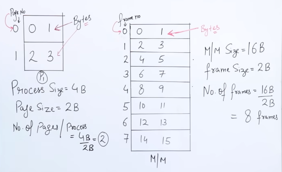
As we know that a process is divided into pages, here we see that we have a process P1 of size 4 bytes. To equally divide the process into pages, we would need 2 pages, each of size 2 bytes, to account for the total process size of 4 bytes.
If there were let's say n number of processes of size 4 bytes, the total number of pages needed would be $$\Sigma_nPage = \frac{Size(Process)}{Size(Page)}$$
And thus all the bits from 0 to 3 are represented in each page.
Which would actually look something like:
| Page | Byte | Byte |
|---|---|---|
| 0000 | 0000 | 0001 |
| 0001 | 0010 | 0011 |
This is called a page table. Each and every process has it's own page table.
Counting 0 itself, we get 4 bits.
Now let's say we have a Main Memory of size 16 bytes and let's say we have a frame size of 2 bytes.
So the total number of frames we can divide the main memory into would be 8 (same formula as for pages.)
So the bits from 0-15 would be stored in something like this :
| Page | Byte | Byte |
|---|---|---|
| 0000 | 0000 | 0001 |
| 0001 | 0010 | 0011 |
| 0010 | 0100 | 0101 |
| 0011 | 0110 | 0111 |
| 0100 | 1000 | 1001 |
| 0101 | 1010 | 1011 |
| 0110 | 1100 | 1101 |
| 0111 | 1110 | 1111 |
2. Address translation in paging.
Paging uses a two-part address: a page number and an offset within the page.
-
Logical Address:
- Divided into two parts:
- Page number (p): Identifies the page within the process’s logical address space.
- Page offset (d): Specifies the exact location within the page.
- For example, if a logical address is 16 bits, the higher bits might represent the page number, and the lower bits the offset.
- Divided into two parts:
-
Physical Address:
- The page number is mapped to a frame using the page table, and the offset is added to reach the exact physical address.
- Formula:
Physical Address = Frame Number + Page Offset
A very nice explanation from stack-overflow as to the clear difference between page number and page offset:
https://stackoverflow.com/questions/15628671/page-number-and-offset
Let me talk around this a bit and hopefully I can be of some help.

First, an analogy - imagine that you're trying to locate a house in a city. Imagine that each house was given a unique number - you can imagine that the number of houses would soon get very large and confusing.

Now imagine that you introduce the concept of streets - the house numbers now become a bit more managable as you've grouped them into nice chunks.

So: Streets = Page number, house number = offset address.
Now sometimes people often confuse page offset with page size.
But :
The page offset is the actual number of bits of the page.
The page size is 2 raised to the power of the page offset.
The Logical address is made up of the addition of page number bits and the page offset bits.
The Logical address space or size of the logical address is 2 raised to the power of the total number of bits in the entire logical address, which is also the size of the entire process.
Example
For example let's say within our page example:
| Page | Byte | Byte |
|---|---|---|
| 0000 | 0000 | 0001 |
| 0001 | 0010 | 0011 |
where 0000 be P0 and 0001 be P1.
Let's say the CPU wants to fetch whatever is in the offset of 0011 or 3 from the main memory.
In the logical address space this is designated by the CPU as :
| Page number | Page offset |
|---|---|
| 1 | 1 |
Where the page number 1 is the page where the desired offset 0011 is residing, which is pointed to by called the page offset 1.
The reason why only a single bit is needed to set the page number, is because the total number of pages are just 2, which can be represented by a single bit.
However for convenience reasons one can also think as:
| Page number | Page offset |
|---|---|
| 0001 | 1 |
And that would be totally correct. We have the offset as a single bit as we don't want it's value, rather, it's index or logical location.
Translation to physical address
Let's say that page P1 is residing in frame 4 or 0100 in the frame table
| 0100 | 1000 | 1001 |
|---|
So the logical address from the page table as 11 will translated to 0100, 1 on the physical address space, by the MMU or memory management unit.
This means the CPU is pointing to 1001 which is the offset of frame 0100. 1001 is the actual value which is retrieved from the main memory.
This is how the translation of logical to physical address works.
For working quickly we can just consider the given formula : Physical Address = Frame Number + Page Offset . We can verify that this formula works, since in our example we had frame number, 0100 or 100, if we ignore preceding 0. And our page offset was 1.
So adding that, we do get the value as 1001 which is the same result.
Numerical 1 for better understanding - Logical address space and Physical address space and pages
A better understanding using a numerical https://www.youtube.com/watch?v=30P73tWmU0s&list=PLxCzCOWd7aiGz9donHRrE9I3Mwn6XdP8p&index=55
So we have a given logical address space of size = 4 GB.
And we have a physical address space of size = 64 mb
We have page sizes given as 4 KB each.
The main memory here is byte-addressable. (What does that mean?)
What we are asked to find is:
- Total number of pages
- Total number of frames
- Number of entries in the page table.
- Size of the page table.
So let's go over the facts we have.
The main memory's smallest unit is a byte, or 4-bits (from the fact that it is byte-addressable.)
So we need to convert all given data in terms of bytes.
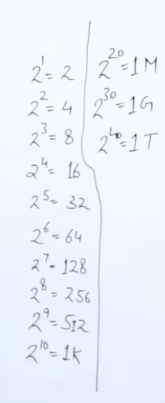
Here's a good unit table to understand which power of 2 corresponds to what:
So the total number of bits or the entire logical address is given as:
Logical address =
Thus we get the Logical address as
Please note that the logical address space or it's size is a different numerical figure as compared to the total number of bits in the logical address itself. The size is always in the power of 2 raised to total number of bits in the logical address.
So for our first question: Total number of pages, we need to find the amount of bits assigned to Page number in the logical address.
But we cannot yet distinguish between the total number of bits assigned to the page number and the page offset.
For that we need to work on the given Page size = 4KB.
From our units table we can gather that 1K =
So the total number of bits in the given page, would be
So the page offset or the actual page address, is assigned to 12 bits.
Now, we can easily get the number of bits assigned to the page number is 32 - 12 = 20 bits.
So we have our logical address as :
| Page number | Page offset |
|---|---|
| 20 bits | 12 bits |
Now coming back to our question:
- Total number of pages = $$\frac{2^{32}}{2^{12}}$$
or
Moving to our second question:
- Total number of frames.
We need to apply similar logic here. We need to find the frame number bits by first finding the Physical address.
Do note that Frame offset is always the same as Page offset.
So we already have part of the answer. Frame offset = 12 bits.
We have given Physical address space/size = 64 MB or
So the physical address is composed of 26 bits.
So subtracting frame offset from this number, we get frame number bits as 26 - 12 = 14 bits
So we have the physical address as :
| Frame number | Frame offset |
|---|---|
| 14 bits | 12 bits |
So,
- Total number of frames =
.
Now, moving to our third question,
- Number of entries in the page table:
The number of entries in our page table will the same as our total number of pages, or
And our last question,
- Size of the page table:
Now we have total
Now we know that each frame number comprises of 14 bits.
So our total size of the page table would be
Numerical 2 for better understanding - Logical address space and Physical address space and pages
https://www.youtube.com/watch?v=L80DakYu4uw&list=PLxCzCOWd7aiGz9donHRrE9I3Mwn6XdP8p&index=56
Let's say we have another question here:
'''
Consider a system which has:
Logical address = 7bits
Physical address = 6bits
Page size = 8 words


Then Calculate the total number of pages and total number of frames


Note: 1 word = 2 bytes or 16 bits or 2^8 bits in a traditional 64-bit system architecture.

'''
Here we have our unit table for reference
So we need to find :
- Total number of pages
- Total number of frames
Addressing the first question,
We need to find the Logical address space, which would be
The given page size is 8 words or 8 bytes. Therefore the page size in bits would be
And the page offset would be 3 bits.
- Therefore the total number of pages would be : $$\frac{2^{7}}{2^{3}}$$ =
pages.
Now addressing the second question, we need to find the physical address space, which would be
Since we know that frame offset = page offset. Therefore we can say that : frame size = page size.
Thus frame size would be
- Therefore the total number of pages would be : $$\frac{2^{6}}{2^{3}}$$
=frames.
3. Page table entry format.
https://www.youtube.com/watch?v=JyPMJnnkNmQ&list=PLxCzCOWd7aiGz9donHRrE9I3Mwn6XdP8p&index=57
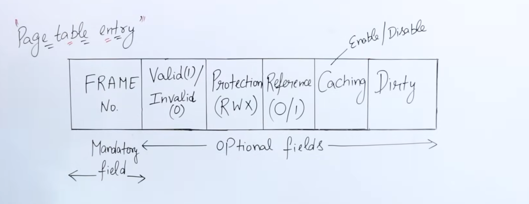
Each entry in the page table has a specific arrangement of bits which have various information regarding that page, and what should be done with that page.
-
The first field in the entry is obviously, the
frame number bit. It is a mandatory field, pointing to the respective frame in which the page resides. -
The second field, represents the
Valid bitorInvalid bit. Thisbitis responsible for indicating whether the page actually is present in the frame or not. If the bit is0, the page is absent and this triggers a page fault. This happens sometimes since when using virtual memory, the system cannot load all pages at once, so pages are loaded/unloaded according to the locality of reference, hence sometimes certain pages could be absent in the cache. -
The third field represents
Read,Write and Execute permissionlevel bits. It's used by the OS to control access to the page's contents. -
The fourth field represents
Reference bitwhich indicates whether the page has been recently accessed or not. This field is relevant to variousPage replacement algorithms, suchLRU,NRU,FIFO,SCetc, which shall be discussed later down the line. -
The fifth field represents the
Caching bit, which indicates whether that page should be cached or not, depending on it'sfrequency of access. It's relevant to stuff such asvirtual memory -> swapping,Page replacement algorithms, etc. -
The sixth and final field represents the
Dirty bit. Let's say that the value of a variablexwithin this page is equal to100. And theRWXsection provides the theWritepermission to aUser1.User1modifies the data ofxto200. However this modification takes place first in main memory. The value is propagated to the hard disk later on since the hard disk's read/write speeds are slower as compared to the main memory. The value is updated to the disk once the CPU is done working with the new value. However here's where the dirty bit comes into play. Before writing to the disk, instead of scanning the entire page for the previous value, the dirty bit (value = 1), informs the system that the page has been modified, and directly updates the value of x on the hard disk with the current value from main memory.
Types of paging
1. Multi-level paging / Hierarchical paging
https://www.youtube.com/watch?v=PiEq1CoP0ds&list=PLxCzCOWd7aiGz9donHRrE9I3Mwn6XdP8p&index=58
This type of paging is needed when the size of the page table exceeds that of frame it's residing in..
Since the pages reside within frames, it would be unrealistic if the frame falls short to accommodate the page table.
So let's say we have a question :
'''
Phyiscal address space = 256 MB
Logical address space = 4 GB
Frame size = 4 KB
Page Table Entry = 2B
'''
Let's start figuring out the deets first.
Here we have our unit table for reference
We have a the Physical address space or the main memory's size = 256 MB.
- So the total bits in the physical address would be
= = 28 bits.
We have our frame size as 4 KB.
- So the total bits in the frame offset and page offset would be
= 12 bits. - Subtracting that from the total bits in P.A we get the frame number bit as
28-12 = 16 bits.
Thus our physical address would be:
| Frame number | Frame offset |
|---|---|
| 16 | 12 |
- Therefore total number of frames in the frame table would be
.
Now we have the logical address space or size given as4 GB. - So the total bits in logical address would be
= 32 bits. - We know that the page offset is of
12bits. - Therefore the page number bits would be
32-12 = 20 bits.
Thus our logical address would be:
| Page number | Page offset |
|---|---|
| 20 | 12 |
- Therefore total number of pages in page table =
.
Now find out the size of our page table.
It is given that the size of each entry of the page table is 2 B.
And we have our number of pages in the page table as
So the total size of the page would be 2 MB.
Now we have a problem.
The given size of a frame is only 4KB however it needs to accommodate a page table of size 2 MB, which exceeds it's capacity.
So what do we do now?
We break down the page table further into another outer page table which could be accommodated in a frame.
So we divide the page table into equal parts of 4 KB.
-
Thus getting total number of pages for the outer page table as : $$\frac{2^{21}}{2^{12}} = 2^9$$
or512pages. -
So the size of the new outer page table would be $$2^9 . 2 = 2^{10}$$ bytes or
1 KB, which can now fit in the frames.Thus the inner page table's each page will have a total entries of $$\frac{2^{12}}{2^1} = 2^{11}$$ or 11 entries
-
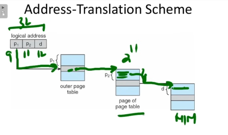
Now the CPU's generated logical address will need to be modified as well.
We know that the logical address bits were
32bits,12of which were the offset bits and20were the page number bits.It was :
| Page number | Page offset |
|---|---|
| 20 | 12 |
However since we divided the page table into an outer page table, that will be reflected in the address as well.
The page number section will be divided into parts. One section for the outer page table, which will map to another section to the inner page table, whose mapping to the frame in turn, will be given by the page offset.
So we have
And we got to know that each page in the inner page table has a total of 11 entries
So our new logical address will be :
| Outer Page number | Inner Page number | Page offset |
|---|---|---|
| 9 | 11 | 12 |
Why is this? Since each page on the outer page table maps to a page within the inner page table, which maps to a particular entry in it, that being the actual frame on the main memory.
This diagram should provide a better explanation.
2. Inverted Paging
https://www.youtube.com/watch?v=spApKfUa8BI&list=PLxCzCOWd7aiGz9donHRrE9I3Mwn6XdP8p&index=59&pp=iAQB
Now there is another type of paging. It did not make that much of a hit however it did solve a very important problem of paging.
In traditional paging every process has it's own page table which is stored in a frame in the main memory.
So let's say a system has 100 processes. So according to traditional paging there will be 100 frames contain 100 page tables each in the main memory each. That's an incredible waste of memory, really kudos to whoever came up with that.
So, to tackle this, inverted paging was introduced. What "inverted" paging does is that flip's the paging table's contents inside out, and adds an addition field.
In traditional paging we had each entry's mandatory part as the frame number.
In inverted paging, it's flipped inside out.
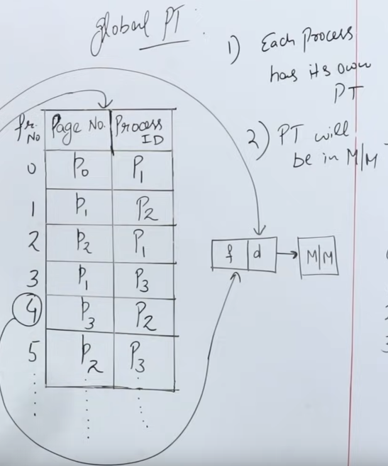
Inverted paging says that : "let there be a global paging table".
The frame numbers are on the outside or index of the paging table.
The total number of entries in the paging table will be the same as the number of frames in the main memory.
So in a main memory of 1024 frames, there will be 1024 entries in the global paging table.
Each entry in the paging table, has two fields.
- The page number.
- The corresponding process using that page.
It is of quintessential importance that while fetching any data from the page table, the CPU structures the logical address in such a way that it specifies both the page number AND the associated process ID.
Since a single page can be acquired by multiple processes.
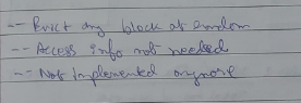
While this method of paging saves a lot of memory by having a single paging table, the problem is that to look up a specific page, we need to search the associated process ID as well, and that too in a linear search way.
I honestly don't know why better search algorithms couldn't be applied here but that's the main reason why inverted search isn't used in mainstream industry.
If you ask me, it's a damn shame we couldn't get the best of both worlds. Or, maybe we did, I just don't happen to know as it's probably out of syllabus.
Protection Mechanisms in Paging
Memory protection in paging prevents processes from accessing each other’s memory, enhancing system security and stability.
-
Access Control Bits:
As we discussed earlier, there are access control bits in each page table entry deciding on access to that entry.- Each page table entry includes protection bits to specify the allowed operations on the page.
- Typical permissions include:
- Read: Only reading is allowed; attempts to write generate an error.
- Write: Writing is allowed, usually combined with read permissions.
- Execute: Allows code execution from the page. If not set, the page cannot be executed as code, preventing certain types of attacks.
-
Protection Faults:
- If a process attempts an operation not permitted by the protection bits, a protection fault occurs (often resulting in a segmentation fault or access violation).
- Protection faults are handled by the operating system, which may terminate the offending process or take corrective action.
-
Kernel and User Modes:
- Memory is typically divided into kernel and user modes. Kernel mode pages can only be accessed by the OS, while user mode pages are accessible to applications.
- This separation ensures that user applications cannot accidentally or maliciously modify critical system data.
Paging Hardware Support
Paging requires specific hardware mechanisms to handle address translation and improve efficiency. Let's explore these in more detail.
1. Page Table Base Register (PTBR)
- The Page Table Base Register (PTBR) is a hardware register that holds the starting address of the page table in memory for the currently running process.
- Each process has its own page table, which is stored in main memory.
- When a process switch occurs (i.e., the CPU switches from executing one process to another), the PTBR is updated to point to the new process's page table.
- The PTBR allows quick access to the page table during address translation, as it tells the system where to find the page table for the current process.
2. Translation Lookaside Buffer (TLB)
https://www.youtube.com/watch?v=Z2T2vnyZl0o&list=PLxCzCOWd7aiGz9donHRrE9I3Mwn6XdP8p&index=65
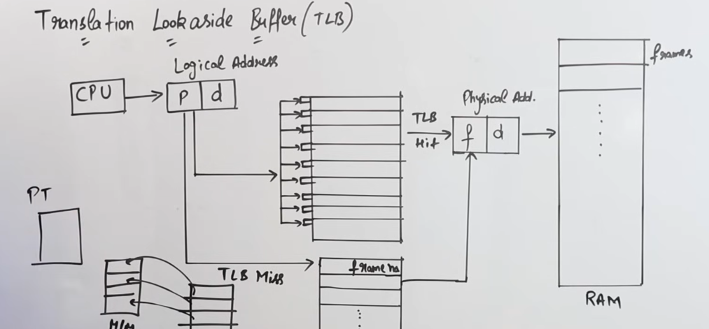
The Translation Lookaside Buffer (TLB) is a special, small, fast cache that stores a subset of page table entries to speed up address translation.
Page Table
So the main problem about traditional paging and multi-level paging is that it requires a lot of time for the CPU to fetch the required data from main memory.
This is because using the logical address the CPU first needs to access the page table, let's say the time taken for that be x units.
Now to find the relevant frame number, which will then point to the required frame in the main memory, the time taken for that will be another x units.
So total time taken would be 2x units.
Now consider, that in case of multi-level paging, that time increases exponentially, thus creating a lot of time lag.
Thus here, the Translation-Lookaside Buffer is introduced to solve the time problem.
The Translation-Lookaside Buffer contains the mapping to all the frame numbers of the main memory.
So the CPU can generate the logical address containing the page number, which can then access the TLB that contains the mapping to the required frame, and then can lead to required frame straight to the main memory, thus avoiding the unnecessary de-tour via the page table.
This is called a TLB-Hit where the required frame mapping was found.
So the time taken for a TLB-Hit would be: Time taken to access TLB + Time taken to access the main memory, also known as the Effective Memory Access Time (EMAT).
In the event that the required frame mapping was not found on the TLB, we need to route through the default paging table to find the required frame. And if it's still not found then it's obviously a page fault.
This is called a TLB-Miss where the required frame mapping was not found.
So the time taken for a TLB-Miss would be: Time taken to access TLB + Time taken to access Paging table + Time taken to access the main memory, also known as the Effective Memory Access Time (EMAT).
3. Multi-Level Paging
As discussed earlier in 1. Multi-level paging / Hierarchical paging, For systems with large virtual address spaces, single-level page tables become impractically large. Multi-level paging reduces memory requirements by dividing the page table into multiple levels.
- Instead of a single page table, multi-level paging uses a hierarchy of tables.
- The outer page table contains pointers to inner page tables, which in turn contain frame numbers or further table pointers.
- When performing a lookup, the system accesses multiple tables in sequence. While this increases the number of memory accesses, TLBs can mitigate the performance impact.
Virtual Memory
Some recap from Computer architecture of last semester.
What is Locality of reference?
There are two ways in which the processor decides by which data should be loaded onto the cache.
This is called locality of reference.
- Spatial Locality
- Temporal Locality
Spatial Locality
Spatial Locality refers to the phenomenon where if a particular memory location is accessed, nearby memory locations are likely to be accessed soon. This principle is used in cache memory design, where data that is close to the recently accessed data, is loaded onto the cache.
Temporal Locality
Temporal locality refers to the likelihood that if a memory location is accessed now, it will probably be accessed again in the near future. This principle is used in cache design where recently accessed memory locations are kept in a fast memory or cache to reduce the required time to access it again.
Inclusion
Inclusion is a property of cache hierarchy in computer architecture that determines whether a subset of superset of the data is present in the next level of memory/cache.
There are two types of cache inclusion:
- Cache inclusion (duh) : A cache is said to be cache-inclusive if it contains a subset of the data present in the next level of cache/main memory. This means that any data present in the case is also present in the next level of cache/main memory.
- Cache exclusion: A cache is said to be cache-exclusive, if it contains a superset of the data present in the next level of cache/main memory. This means any data present in the cache is not present in the level of cache/main memory.
Cache inclusion simplifies and improves cache coherence and performance.
But it can increase cache size and access time as cache needs to store a large amount of time.
Cache coherence
It is a concept in computer architecture that data in multiple caches of a multiprocessor architecture should be consistent and up-to-date. When multiple processors access the same memory location, they may have their own local cache with different copies of the same data. Cache coherence ensures that when one processor modifies the data, changes are propagated to all other caches in the system.
This is important because if the caches are not kept coherent a processor will be working with outdated data, leading to inconsistencies and incorrect results. Cache coherence is maintained through various protocols, such as sweeping, directory based and message-based protocols.
Now, onwards to the topic of Virtual Memory.
https://www.youtube.com/watch?v=o2_iCzS9-ZQ&list=PLxCzCOWd7aiGz9donHRrE9I3Mwn6XdP8p&index=64
So what is virtual memory?
Just like happiness, it is an illusion to the CPU that there is more memory available than the physical memory to accommodate processes of size that are much greater than the main memory.
So how does happi-, sorry this illusion of greater memory work?
It works by using page replacement algorithms.
We know that a system can have a lot of processes. Each of the processes can share a lot of pages together.
So it is nigh-impossible to keep all the pages in the main memory at once.
So here the page replacement algorithms, work alongside the locality of reference, to decide which page should be fetched and which replaced. And how it's done totally depends on the page replacement algorithm used.
This constant replacement of pages gives the CPU a very happy illusion that it has access to a vast amount of memory for all it's processes.
Here's an example run of how it works.
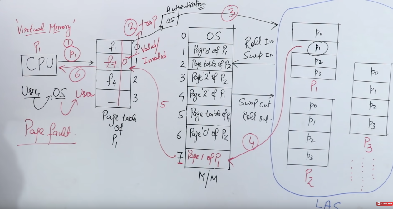
Let's say the CPU wants to access Page 1 of Process 1.
So it first checks the page table, or maybe the TLB, to check whether the relevant page-to-frame mapping exists or not.
If it does contain, then the CPU can right away access that frame and then the page of that particular process.
However in the event of the relevant page-to-frame mapping not existing in the page table/TLB, then a page fault is triggered, and the CPU then has to directly access the hard disk and fetch the page from there, into the main memory. The time taken for this is called the page fault service time.
So the Effective Memory Access Time (EMAT) in this case would be :
Let p be the probability of a page fault occurring (we would generally consider it
Then, EMAT = p(Page Fault service time) + (1-p)(Main memory access time).
Even if the probability is 50% of
And then we can find the time needed to hit the main memory after having found the relevant frame number using the second half of the formula.
Important note: The main memory access time is usually in nanoseconds, while the page fault service time is usually in miliseconds.
Since in order to address the page fault we need to go through the page table/ TLB first then to the main memory, which incurs a delay, as compared to accessing the main memory straight away.
- Sometimes while addressing the page fault service time, we need to add in the time to access main memory as well, since the page is first brought over to main memory from disk, then the CPU has to initiate a search again for that page, to find the frame where that page was loaded on to.
What is working set in virtual memory?
In virtual memory, a working set is the set of pages that a process needs to keep in memory at a particular time to run efficiently without causing frequent page faults.
For example the pages of the essential base programs of the OS, they are needed to be kept in memory all at the same time for a particular time in order for the OS to not crash and cause page faults etc.
Here’s a breakdown:
-
Definition: The working set represents a "snapshot" of the pages actively being used by a process over a certain window of time. It’s a dynamic set, changing as the process accesses different parts of its address space.
-
Working Set Window (τ): This window, often denoted by τ (tau), represents a specific timeframe or number of memory references. Pages accessed within this timeframe make up the working set. If the process references new pages over time, these pages enter the working set, while older, unused pages exit.
-
Purpose: The working set concept helps the operating system decide which pages to keep in memory and which to swap out, aiming to keep a minimal, efficient amount of memory usage. By keeping only the working set of pages loaded, the system can reduce page faults while maximizing memory utilization.
-
Practical Impact: By estimating the working set, an OS can make better paging decisions, leading to smoother performance. If the working set is too large to fit into RAM, thrashing can occur as pages are constantly swapped in and out.
So, in summary, the working set reflects a process’s "essential" pages for a given period, helping balance memory use and performance in virtual memory systems.
Page Replacement algorithms
Some of the content will be carried from the notes of Computer architecture from last semester, and those will be expanded on further.
Back then it was known to us as Cache-Replacement policies. Now we know much better as to what really gets replaced.
Still let's remember, why we need these replacement algorithms.
What is Cache Page Replacement?
Cache Page replacement is required when the cache suffers from either conflict or cache miss. the process sizes exceed that of main memory, so using virtual memory we have swap some pages out for some other pages. This keeps on happening on demand so that every process is served.
In cache page replacement we evict one block page and make space for the newly requested block page.
Which block Page to replace?
In DMM(Direct Memory mapping), no need for policies.
Under Associative and Set associative mapping, cache page replacement policies are needed.
Types of cache replacement policies
Random Replacement(Not in syllabus this time)- FIFO and
LIFO - Optimal Replacement
- Recency based policies (LRU, NRU)
- Second Chance (SC).
This is what I wrote back then, as I was in a time crunch. Here I will explain these much better.
I will still include the content from the algorithms not in our syllabus this time, for the particular curious cat.
1. Random Replacement Algorithm
2. FIFO Replacement algorithm

Do note the formula for finding hit and miss ratio in this pic. That doesn't change.
This was the content from last semester. If it feels rushed, here is a better explanation this time.
https://www.youtube.com/watch?v=8rcUs5RutX0&list=PLxCzCOWd7aiGz9donHRrE9I3Mwn6XdP8p&index=67
So just like in a queue, where the policy of first-in-first-out works, it's the same here as well.
So the CPU sends a reference string of the frames it needs. In reality each process doesn't get a fixed frame, but for simplicity and example purposes, we consider a fixed frame per process here.

Now let's say for the pages of process P1, three frames f1, f2 and f3 have been allocated.
So applying the FIFO page replacement algorithm, we would get:
So here's how it works :
- The replacement works frame by frame. First we replace frame 1, then frame 2 then frame 3, then frame 1 all over again.
- The replacement only happens if all the frames are full, and there is a page fault detected,
- If there is a page hit, the frames are copied as they are forward (in reality, nothing happens to the frames in case of a hit in that instance, they just stay as they are).
So we start for page 7.
Seeing that initially all frames are empty, it is considered a page miss, so page 7 is written on to frame 1.
| Frames | Pages | Pages | Pages | Pages | Pages | Pages | Pages | Pages | Pages | Pages | Pages |
|---|---|---|---|---|---|---|---|---|---|---|---|
| f3 | |||||||||||
| f2 | |||||||||||
| f1 | 7 | ||||||||||
| Remark | Miss |
Next up is page 0, and since it doesn't exist in main memory, page 0 is written onto frame 2.
| Frames | Pages | Pages | Pages | Pages | Pages | Pages | Pages | Pages | Pages | Pages | Pages |
|---|---|---|---|---|---|---|---|---|---|---|---|
| f3 | |||||||||||
| f2 | 0 | ||||||||||
| f1 | 7 | 7 | |||||||||
| Remark | Miss | Miss |
Similarly for page 1, it's written onto frame 3.
| Frames | Pages | Pages | Pages | Pages | Pages | Pages | Pages | Pages | Pages | Pages | Pages |
|---|---|---|---|---|---|---|---|---|---|---|---|
| f3 | 1 | ||||||||||
| f2 | 0 | 0 | |||||||||
| f1 | 7 | 7 | 7 | ||||||||
| Remark | Miss | Miss | Miss |
Next up we have page 2. It's not present in any frames, so it's a miss. Page 2 is brought over from disk and written on to frame 1, as the last modified frame was frame 3, so it's frame 1's turn now.
| Frames | Pages | Pages | Pages | Pages | Pages | Pages | Pages | Pages | Pages | Pages | Pages |
|---|---|---|---|---|---|---|---|---|---|---|---|
| f3 | 1 | 1 | |||||||||
| f2 | 0 | 0 | 0 | ||||||||
| f1 | 7 | 7 | 7 | 2 | |||||||
| Remark | Miss | Miss | Miss | Miss |
After that we have page 0, which exists in frame 2, so it's a hit. Ideally nothing happens to the frames on a hit, but here we will just copy the values over
| Frames | Pages | Pages | Pages | Pages | Pages | Pages | Pages | Pages | Pages | Pages | Pages |
|---|---|---|---|---|---|---|---|---|---|---|---|
| f3 | 1 | 1 | 1 | ||||||||
| f2 | 0 | 0 | 0 | 0 | |||||||
| f1 | 7 | 7 | 7 | 2 | 2 | ||||||
| Remark | Miss | Miss | Miss | Miss | Hit |
Next up we have page 3, it doesn't exist, so it's a miss. It's written over on to frame 2.
| Frames | Pages | Pages | Pages | Pages | Pages | Pages | Pages | Pages | Pages | Pages | Pages |
|---|---|---|---|---|---|---|---|---|---|---|---|
| f3 | 1 | 1 | 1 | 1 | |||||||
| f2 | 0 | 0 | 0 | 0 | 3 | ||||||
| f1 | 7 | 7 | 7 | 2 | 2 | 2 | |||||
| Remark | Miss | Miss | Miss | Miss | Hit | Miss |
Next up have page 0, it doesn't exist, so it's a miss. It's written over on to frame 3
| Frames | Pages | Pages | Pages | Pages | Pages | Pages | Pages | Pages | Pages | Pages | Pages |
|---|---|---|---|---|---|---|---|---|---|---|---|
| f3 | 1 | 1 | 1 | 1 | 0 | ||||||
| f2 | 0 | 0 | 0 | 0 | 3 | 3 | |||||
| f1 | 7 | 7 | 7 | 2 | 2 | 2 | 2 | ||||
| Remark | Miss | Miss | Miss | Miss | Hit | Miss | Miss |
Next we have page 4, it doesn't exist, so it's a miss. It's written over on to frame 1.
| Frames | Pages | Pages | Pages | Pages | Pages | Pages | Pages | Pages | Pages | Pages | Pages |
|---|---|---|---|---|---|---|---|---|---|---|---|
| f3 | 1 | 1 | 1 | 1 | 0 | 0 | |||||
| f2 | 0 | 0 | 0 | 0 | 3 | 3 | 3 | ||||
| f1 | 7 | 7 | 7 | 2 | 2 | 2 | 2 | 4 | |||
| Remark | Miss | Miss | Miss | Miss | Hit | Miss | Miss | Miss |
Next we have page 2, it doesn't exist, so it's a miss. It's written over on to frame 2.
| Frames | Pages | Pages | Pages | Pages | Pages | Pages | Pages | Pages | Pages | Pages | Pages |
|---|---|---|---|---|---|---|---|---|---|---|---|
| f3 | 1 | 1 | 1 | 1 | 0 | 0 | 0 | ||||
| f2 | 0 | 0 | 0 | 0 | 3 | 3 | 3 | 2 | |||
| f1 | 7 | 7 | 7 | 2 | 2 | 2 | 2 | 4 | 4 | ||
| Remark | Miss | Miss | Miss | Miss | Hit | Miss | Miss | Miss | Miss |
Next we have page 3, it doesn't exist, so it's a miss. It's written over on to frame 3.
| Frames | Pages | Pages | Pages | Pages | Pages | Pages | Pages | Pages | Pages | Pages | Pages |
|---|---|---|---|---|---|---|---|---|---|---|---|
| f3 | 1 | 1 | 1 | 1 | 0 | 0 | 0 | 3 | |||
| f2 | 0 | 0 | 0 | 0 | 3 | 3 | 3 | 2 | 2 | ||
| f1 | 7 | 7 | 7 | 2 | 2 | 2 | 2 | 4 | 4 | 4 | |
| Remark | Miss | Miss | Miss | Miss | Hit | Miss | Miss | Miss | Miss | Miss |
Next up we have page 0, it doesn't exist, so it's a miss. It's written over on to frame 1.
| Frames | Pages | Pages | Pages | Pages | Pages | Pages | Pages | Pages | Pages | Pages | Pages |
|---|---|---|---|---|---|---|---|---|---|---|---|
| f3 | 1 | 1 | 1 | 1 | 0 | 0 | 0 | 3 | 3 | ||
| f2 | 0 | 0 | 0 | 0 | 3 | 3 | 3 | 2 | 2 | 2 | |
| f1 | 7 | 7 | 7 | 2 | 2 | 2 | 2 | 4 | 4 | 4 | 0 |
| Remark | Miss | Miss | Miss | Miss | Hit | Miss | Miss | Miss | Miss | Miss | Miss |
Next up, we have page 3. it exists, so it's a hit. We will just copy over the values to the next iteration.
This table is a continuation from the last column, as extending that table would not render it fully in a pdf.
| Frames | Pages | Pages | Pages | Pages | Pages | Pages |
|---|---|---|---|---|---|---|
| f3 | 3 | 3 | ||||
| f2 | 2 | 2 | ||||
| f1 | 0 | 0 | ||||
| Remark | Miss | Hit |
Next up we have page 1. It doesn't exist, so it's a miss. It's written over on to frame 2.
| Frames | Pages | Pages | Pages | Pages | Pages | Pages |
|---|---|---|---|---|---|---|
| f3 | 3 | 3 | 3 | |||
| f2 | 2 | 2 | 1 | |||
| f1 | 0 | 0 | 0 | |||
| Remark | Miss | Hit | Miss |
Next up we have page 2. It doesn't exist, so it's a miss. It' written over on to frame 3.
| Frames | Pages | Pages | Pages | Pages | Pages | Pages |
|---|---|---|---|---|---|---|
| f3 | 3 | 3 | 3 | 2 | ||
| f2 | 2 | 2 | 1 | 1 | ||
| f1 | 0 | 0 | 0 | 0 | ||
| Remark | Miss | Hit | Miss | Miss |
The final page, is page 0. It exists, so it's a hit. So we just copy over the values.
| Frames | Pages | Pages | Pages | Pages | Pages | Pages |
|---|---|---|---|---|---|---|
| f3 | 3 | 3 | 3 | 2 | 2 | __ |
| f2 | 2 | 2 | 1 | 1 | 1 | __ |
| f1 | 0 | 0 | 0 | 0 | 0 | __ |
| Remark | Miss | Hit | Miss | Miss | Hit | __ |
Important Note: It's essential to know that in real time, in a computer, there isn't any infinitely expanding table where values are replaced like this. This will all happen in a single frame table in the main memory. The table expansion here is shown to depict what happens over time.
3. LIFO
4. Optimal Replacement Algorithm.

If this explanation feels rushed, here is a better explanation:
https://www.youtube.com/watch?v=q2BpMvPhhrY&list=PLxCzCOWd7aiGz9donHRrE9I3Mwn6XdP8p&index=69
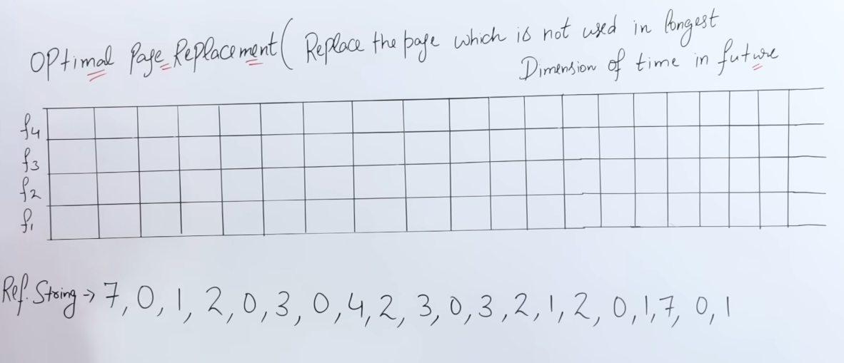
Let's say we have 4 frames this time, and the CPU has given us a reference string for required pages.
Optimal page replacement algorithm works by replacing the page which won't be needed for the longest amount of time in the future.
So we continue, business as usual, till page 2, where all frames are filled up.
| Frames | Pages | Pages | Pages | Pages | Pages | Pages | Pages | Pages | Pages | Pages | Pages |
|---|---|---|---|---|---|---|---|---|---|---|---|
| f4 | 2 | ||||||||||
| f3 | 1 | 1 | |||||||||
| f2 | 0 | 0 | 0 | ||||||||
| f1 | 7 | 7 | 7 | 7 | |||||||
| Remark | Miss | Miss | Miss | Miss |
Now the next page is page 0, it exists, so it's a hit.
| Frames | Pages | Pages | Pages | Pages | Pages | Pages | Pages | Pages | Pages | Pages | Pages |
|---|---|---|---|---|---|---|---|---|---|---|---|
| f4 | 2 | 2 | |||||||||
| f3 | 1 | 1 | 1 | ||||||||
| f2 | 0 | 0 | 0 | 0 | |||||||
| f1 | 7 | 7 | 7 | 7 | 7 | ||||||
| Remark | Miss | Miss | Miss | Miss | Hit |
Now the next page, is 3, it doesn't exist, so it's a miss. And all our frames are full.
So now the CPU needs to decided which page needs to be replaced.
So checking the reference string:
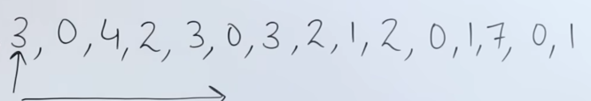
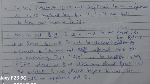
We see that from page 3 onwards the page which is not in demand or use, is page 7. It is reused at a very later point in time.
So we replace page 7 with page 3.
| Frames | Pages | Pages | Pages | Pages | Pages | Pages | Pages | Pages | Pages | Pages | Pages |
|---|---|---|---|---|---|---|---|---|---|---|---|
| f4 | 2 | 2 | 2 | ||||||||
| f3 | 1 | 1 | 1 | 1 | |||||||
| f2 | 0 | 0 | 0 | 0 | 0 | ||||||
| f1 | 7 | 7 | 7 | 7 | 7 | 3 | |||||
| Remark | Miss | Miss | Miss | Miss | Hit | Miss |
Next up we have a hit for page 0, so we copy over the values as they are:
| Frames | Pages | Pages | Pages | Pages | Pages | Pages | Pages | Pages | Pages | Pages | Pages |
|---|---|---|---|---|---|---|---|---|---|---|---|
| f4 | 2 | 2 | 2 | 2 | |||||||
| f3 | 1 | 1 | 1 | 1 | 1 | ||||||
| f2 | 0 | 0 | 0 | 0 | 0 | 0 | |||||
| f1 | 7 | 7 | 7 | 7 | 7 | 3 | 3 | ||||
| Remark | Miss | Miss | Miss | Miss | Hit | Miss | Hit |
Up next we have page 4, it's a miss.
We see that
Starting from page 4, the most used pages are 2, 3 and 0. Page 1 is reused a little later.
So we can safely replace page 1 with page 4.
| Frames | Pages | Pages | Pages | Pages | Pages | Pages | Pages | Pages | Pages | Pages | Pages |
|---|---|---|---|---|---|---|---|---|---|---|---|
| f4 | 2 | 2 | 2 | 2 | 2 | ||||||
| f3 | 1 | 1 | 1 | 1 | 1 | 4 | |||||
| f2 | 0 | 0 | 0 | 0 | 0 | 0 | 0 | ||||
| f1 | 7 | 7 | 7 | 7 | 7 | 3 | 3 | 3 | |||
| Remark | Miss | Miss | Miss | Miss | Hit | Miss | Hit | Miss |
For next pages 2 and 3 and 0 are all hits.
| Frames | Pages | Pages | Pages | Pages | Pages | Pages | Pages | Pages | Pages | Pages | Pages |
|---|---|---|---|---|---|---|---|---|---|---|---|
| f4 | 2 | 2 | 2 | 2 | 2 | 2 | 2 | 2 | |||
| f3 | 1 | 1 | 1 | 1 | 1 | 4 | 4 | 4 | 4 | ||
| f2 | 0 | 0 | 0 | 0 | 0 | 0 | 0 | 0 | 0 | 0 | |
| f1 | 7 | 7 | 7 | 7 | 7 | 3 | 3 | 3 | 3 | 3 | 3 |
| Remark | Miss | Miss | Miss | Miss | Hit | Miss | Hit | Miss | Hit | Hit | Hit |
Continuing our table :
We see that
Pages 3, 2 are hits as well
| Frames | Pages | Pages | Pages |
|---|---|---|---|
| f4 | 2 | 2 | 2 |
| f3 | 4 | 4 | 4 |
| f2 | 0 | 0 | 0 |
| f1 | 3 | 3 | 3 |
| Remark | Hit | Hit | Hit |
Now see that page 1 is a miss.
From page 1 onwards the most used pages are 2 and 0. That leaves out pages 4 and 3 to be replaceable.
We can choose to replace either page 4 or page 3.
Let's replace page 4.
| Frames | Pages | Pages | Pages | Pages | |||||
|---|---|---|---|---|---|---|---|---|---|
| f4 | 2 | 2 | 2 | 2 | |||||
| f3 | 4 | 4 | 4 | 1 | |||||
| f2 | 0 | 0 | 0 | 0 | |||||
| f1 | 3 | 3 | 3 | 3 | |||||
| Remark | Hit | Hit | Hit | Miss |
Next up, pages 2, 0 and 1 are all hits.
| Frames | Pages | Pages | Pages | Pages | Pages | Pages | Pages | ||
|---|---|---|---|---|---|---|---|---|---|
| f4 | 2 | 2 | 2 | 2 | 2 | 2 | 2 | ||
| f3 | 4 | 4 | 4 | 1 | 1 | 1 | 1 | ||
| f2 | 0 | 0 | 0 | 0 | 0 | 0 | 0 | ||
| f1 | 3 | 3 | 3 | 3 | 3 | 3 | 3 | ||
| Remark | Hit | Hit | Hit | Miss | Hit | Hit | Hit |
Up next we have page 7, which is a miss.
Checking our reference string again,
We see that
From page 7 onwards, pages 0 and 1 are needed. That leaves out pages 3 and 2.
Let's replace page 3 with page 7.
| Frames | Pages | Pages | Pages | Pages | Pages | Pages | Pages | Pages | ||
|---|---|---|---|---|---|---|---|---|---|---|
| f4 | 2 | 2 | 2 | 2 | 2 | 2 | 2 | 2 | ||
| f3 | 4 | 4 | 4 | 1 | 1 | 1 | 1 | 1 | ||
| f2 | 0 | 0 | 0 | 0 | 0 | 0 | 0 | 0 | ||
| f1 | 3 | 3 | 3 | 3 | 3 | 3 | 3 | 7 | ||
| Remark | Hit | Hit | Hit | Miss | Hit | Hit | Hit | Miss |
And lastly pages 0 and 1 are hits.
| Frames | Pages | Pages | Pages | Pages | Pages | Pages | Pages | Pages | Pages | Pages |
|---|---|---|---|---|---|---|---|---|---|---|
| f4 | 2 | 2 | 2 | 2 | 2 | 2 | 2 | 2 | 2 | 2 |
| f3 | 4 | 4 | 4 | 1 | 1 | 1 | 1 | 1 | 1 | 1 |
| f2 | 0 | 0 | 0 | 0 | 0 | 0 | 0 | 0 | 0 | 0 |
| f1 | 3 | 3 | 3 | 3 | 3 | 3 | 3 | 7 | 7 | 7 |
| Remark | Hit | Hit | Hit | Miss | Hit | Hit | Hit | Miss | Hit | Hit |
So there are 11 page hits and 8 page faults/misses.
Total number of references = 20
The miss ratio = $$\frac{8}{20} . 100% = 40%$$
The hit ratio would then be
The main problem with this algorithm is the lookahead time incurred while checking for relevant pages. And extra memory overhead as well, although that could potentially be solved using some memory-bound search algorithms.
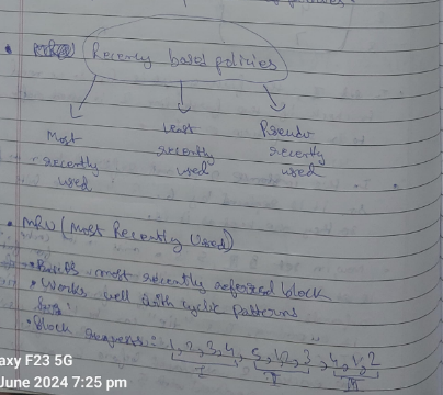
Recency Based Page replacement algorithms.
These algorithms operate on the basis of "recently used". The variants replace pages on varying degrees of recency.
That's the stuff from last semester. If the explanation feels rushed, here is a more in depth explanation.
https://www.youtube.com/watch?v=dYIoWkCvd6A&list=PLxCzCOWd7aiGz9donHRrE9I3Mwn6XdP8p&index=70
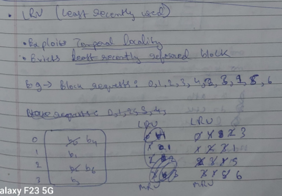
1. Least Recently Used Page Replacement Algorithm.
This algorithm works by replacing pages which have been least recently used (or used in the past).
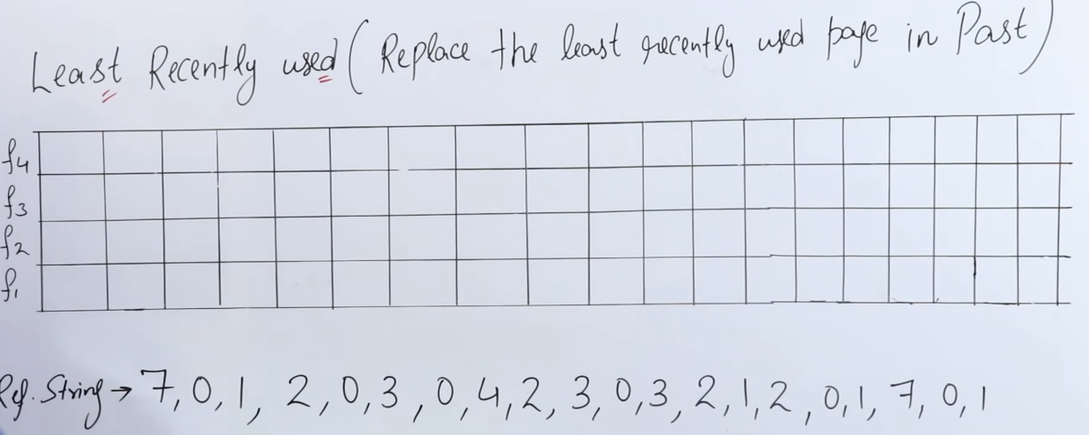
Same reference string again.
So we continue in the same manner till all the frames are filled up.
| Frames | Pages | Pages | Pages | Pages | Pages | Pages | Pages | Pages | Pages | Pages | Pages |
|---|---|---|---|---|---|---|---|---|---|---|---|
| f4 | 2 | ||||||||||
| f3 | 1 | 1 | |||||||||
| f2 | 0 | 0 | 0 | ||||||||
| f1 | 7 | 7 | 7 | 7 | |||||||
| Remark | Miss | Miss | Miss | Miss |
Now the next page is page 0, it exists, so it's a hit.
| Frames | Pages | Pages | Pages | Pages | Pages | Pages | Pages | Pages | Pages | Pages | Pages |
|---|---|---|---|---|---|---|---|---|---|---|---|
| f4 | 2 | 2 | |||||||||
| f3 | 1 | 1 | 1 | ||||||||
| f2 | 0 | 0 | 0 | 0 | |||||||
| f1 | 7 | 7 | 7 | 7 | 7 | ||||||
| Remark | Miss | Miss | Miss | Miss | Hit |
Next page is 3, which is not present, so it's a miss.
Checking our reference string again,
We see that
Up till page 3, the least recently used page is page 7, which was only once needed initially.
So we replace page 7 with page 3.
| Frames | Pages | Pages | Pages | Pages | Pages | Pages | Pages | Pages | Pages | Pages | Pages |
|---|---|---|---|---|---|---|---|---|---|---|---|
| f4 | 2 | 2 | 2 | ||||||||
| f3 | 1 | 1 | 1 | 1 | |||||||
| f2 | 0 | 0 | 0 | 0 | 0 | ||||||
| f1 | 7 | 7 | 7 | 7 | 7 | 3 | |||||
| Remark | Miss | Miss | Miss | Miss | Hit | Miss |
Next up is page 0, which is a hit
| Frames | Pages | Pages | Pages | Pages | Pages | Pages | Pages | Pages | Pages | Pages | Pages |
|---|---|---|---|---|---|---|---|---|---|---|---|
| f4 | 2 | 2 | 2 | 2 | |||||||
| f3 | 1 | 1 | 1 | 1 | 1 | ||||||
| f2 | 0 | 0 | 0 | 0 | 0 | 0 | |||||
| f1 | 7 | 7 | 7 | 7 | 7 | 3 | 3 | ||||
| Remark | Miss | Miss | Miss | Miss | Hit | Miss | Hit |
Next up is page 4 which is a miss.
Checking our reference string again,
We see that the least recently used page is page 1.
So we replace page 1 with page 4
| Frames | Pages | Pages | Pages | Pages | Pages | Pages | Pages | Pages | Pages | Pages | Pages |
|---|---|---|---|---|---|---|---|---|---|---|---|
| f4 | 2 | 2 | 2 | 2 | 2 | ||||||
| f3 | 1 | 1 | 1 | 1 | 1 | 4 | |||||
| f2 | 0 | 0 | 0 | 0 | 0 | 0 | 0 | ||||
| f1 | 7 | 7 | 7 | 7 | 7 | 3 | 3 | 3 | |||
| Remark | Miss | Miss | Miss | Miss | Hit | Miss | Hit | Miss |
Following that, pages 2, 3, 0 , 3, 2 are all hits.
| Frames | Pages | Pages | Pages | Pages | Pages | Pages | Pages | Pages | Pages | Pages | Pages |
|---|---|---|---|---|---|---|---|---|---|---|---|
| f4 | 2 | 2 | 2 | 2 | 2 | 2 | 2 | 2 | |||
| f3 | 1 | 1 | 1 | 1 | 1 | 4 | 4 | 4 | 4 | ||
| f2 | 0 | 0 | 0 | 0 | 0 | 0 | 0 | 0 | 0 | 0 | |
| f1 | 7 | 7 | 7 | 7 | 7 | 3 | 3 | 3 | 3 | 3 | 3 |
| Remark | Miss | Miss | Miss | Miss | Hit | Miss | Hit | Miss | Hit | Hit | Hit |
This table is a continuation of the previous table.
| Frames | Pages | Pages |
|---|---|---|
| f4 | 2 | 2 |
| f3 | 4 | 4 |
| f2 | 0 | 0 |
| f1 | 3 | 3 |
| Remark | Hit | Hit |
After that we have page 1, which is a miss.
Checking our reference string till page 1.
We see that the least recently used page is page 4.
So we replace page 4 with page 1.
| Frames | Pages | Pages | Pages | Pages | Pages | Pages | Pages | Pages | Pages |
|---|---|---|---|---|---|---|---|---|---|
| f4 | 2 | 2 | 2 | ||||||
| f3 | 4 | 4 | 1 | ||||||
| f2 | 0 | 0 | 0 | ||||||
| f1 | 3 | 3 | 3 | ||||||
| Remark | Hit | Hit | Miss |
Following that, we have pages : 2, 0 and 1 as hits.
| Frames | Pages | Pages | Pages | Pages | Pages | Pages | Pages | Pages | Pages |
|---|---|---|---|---|---|---|---|---|---|
| f4 | 2 | 2 | 2 | 2 | 2 | 2 | |||
| f3 | 4 | 4 | 1 | 1 | 1 | 1 | |||
| f2 | 0 | 0 | 0 | 0 | 0 | 0 | |||
| f1 | 3 | 3 | 3 | 3 | 3 | 3 | |||
| Remark | Hit | Hit | Miss | Hit | Hit | Hit |
Now we have page 7 again, which is a miss.
So we check our reference string.

The least recently used page was page 3.
So we replace page 3 with page 7.
| Frames | Pages | Pages | Pages | Pages | Pages | Pages | Pages | Pages | Pages |
|---|---|---|---|---|---|---|---|---|---|
| f4 | 2 | 2 | 2 | 2 | 2 | 2 | 2 | ||
| f3 | 4 | 4 | 1 | 1 | 1 | 1 | 1 | ||
| f2 | 0 | 0 | 0 | 0 | 0 | 0 | 0 | ||
| f1 | 3 | 3 | 3 | 3 | 3 | 3 | 7 | ||
| Remark | Hit | Hit | Miss | Hit | Hit | Hit | Miss |
And lastly pages 0 and 1 are hits.
| Frames | Pages | Pages | Pages | Pages | Pages | Pages | Pages | Pages | Pages |
|---|---|---|---|---|---|---|---|---|---|
| f4 | 2 | 2 | 2 | 2 | 2 | 2 | 2 | 2 | 2 |
| f3 | 4 | 4 | 1 | 1 | 1 | 1 | 1 | 1 | 1 |
| f2 | 0 | 0 | 0 | 0 | 0 | 0 | 0 | 0 | 0 |
| f1 | 3 | 3 | 3 | 3 | 3 | 3 | 7 | 7 | 7 |
| Remark | Hit | Hit | Miss | Hit | Hit | Hit | Miss | Hit | Hit |
Hit and ratios will be the same as before since we have the same reference string.
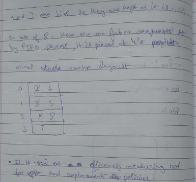
2. Not Recently Used Page replacement algorithm.
Let's use our same reference string.

In NRU, each page is classified based on its "recently used" status. Typically, NRU marks pages with a "referenced" bit, which is periodically reset (like at the start of each clock cycle). When a page needs to be replaced, NRU removes a page that hasn't been "recently used." The idea is that if a page hasn’t been accessed recently, it’s likely safe to replace.
-
Referenced Bit: This bit is set to
1when a page is accessed and periodically reset to0. When replacement is needed, any page with a0can be replaced. -
Replacement Policy: If there are multiple pages with
0, one of them is selected randomly (in basic NRU implementations).
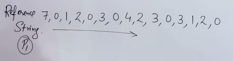
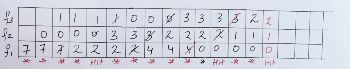
2. Setup:
Imagine we have 4 frames (f1, f2, f3, f4) and a sequence of pages coming in, such as 7, 0, 1, 2, 0, 3, 0, 4, .... We mark each page with a referenced bit.
Step-by-Step Breakdown:
Step 1: Filling Up Frames Initially (All Misses)
-
Page 7:
- No pages in memory, so
7is loaded intof1with its referenced bit set to1. - Result: Miss
- No pages in memory, so
-
Page 0:
0is loaded intof2with its referenced bit set to1.- Result: Miss
-
Page 1:
1is loaded intof3with its referenced bit set to1.- Result: Miss
-
Page 2:
2is loaded intof4with its referenced bit set to1.- Result: Miss
Current State:
| Frame | Page | Ref Bit |
|-------|------|---------|
| f1    | 7    | 1       |
| f2    | 0    | 1       |
| f3    | 1    | 1       |
| f4    | 2    | 1       |
Step 2: Continuing with Hits and Misses
-
Page 0:
0is already inf2, so it's a hit. We set the referenced bit of0to1(if it wasn’t already).- Result: Hit
-
Page 3:
3is not in memory, so it’s a miss.- We need to replace a page. NRU will look for a page with the referenced bit
0to replace. - Since all pages currently have a
1in their referenced bits, NRU will clear all reference bits to0and choose any page randomly. - Let's say
7(inf1) is chosen for replacement. - Replace
7with3and set its referenced bit to1.
Current State:
| Frame | Page | Ref Bit |
|-------|------|---------|
| f1    | 3    | 1       |
| f2    | 0    | 1       |
| f3    | 1    | 0       |
| f4    | 2    | 0       |
- Result: Miss
Step 3: More Misses and Replacement
-
Page 4:
4is not in memory, so it’s a miss.- Again, NRU will look for pages with a referenced bit of
0. - Pages
1and2both have0bits, so we can replace one of them (randomly). - Let’s say we replace
1(inf3) with4, and set its referenced bit to1.
Current State:
| Frame | Page | Ref Bit |
|-------|------|---------|
| f1    | 3    | 1       |
| f2    | 0    | 1       |
| f3    | 4    | 1       |
| f4    | 2    | 0       |
- Result: Miss
- Pages 2, 3, 0, 3, 2:
- These pages are all present in memory, so each access is a hit.
- Each time, we reset the referenced bit to
1for the accessed page.
State after hits:
| Frame | Page | Ref Bit |
|-------|------|---------|
| f1    | 3    | 1       |
| f2    | 0    | 1       |
| f3    | 4    | 1       |
| f4    | 2    | 1       |
Step 4: Introducing New Pages and Replacements
-
Page 1:
1is not in memory, so it’s a miss.- We need to find a page with
0in its referenced bit, but since all pages have1, NRU will reset all reference bits to0and choose one page randomly. - Let’s say
4(inf3) is replaced with1, and we set its referenced bit to1.
Current State:
| Frame | Page | Ref Bit |
|-------|------|---------|
| f1    | 3    | 0       |
| f2    | 0    | 0       |
| f3    | 1    | 1       |
| f4    | 2    | 0       |
- Result: Miss
Final Steps: Finishing the Sequence
-
Pages 2, 0, and 1:
- These are all in memory, so each one is a hit.
- We set the referenced bit to
1for each page on access.
-
Page 7:
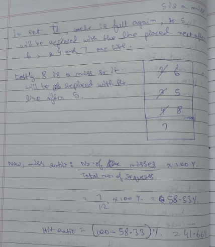
7is not in memory, so it’s a miss.- NRU looks for a page with a
0bit to replace. - We can choose
3(inf1) since it has a0. - Replace
3with7and set its referenced bit to1.
Current State:
| Frame | Page | Ref Bit |
|-------|------|---------|
| f1    | 7    | 1       |
| f2    | 0    | 1       |
| f3    | 1    | 1       |
| f4    | 2    | 1       |
-
Result: Miss
-
Final Pages 0 and 1:
- Both are hits since they’re in memory.
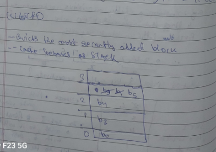
3. Second Chance Page Replacement algorithm
The Second Chance algorithm is similar to FIFO, but with an additional "second chance" for pages with a recently used bit set to 1. It’s often visualized as a "clock" because it processes pages in a circular queue.
- Referenced Bit: Each page has a referenced bit (similar to NRU). When a page is accessed, its referenced bit is set to
1. - Replacement Policy: When a page needs to be replaced, the algorithm checks the referenced bit of pages in a circular manner:
- If the referenced bit is
0, the page is replaced. - If the referenced bit is
1, it gets a "second chance": the algorithm resets the bit to0and moves to the next page.
- If the referenced bit is
2. Setup
We’ll assume we have 4 frames (f1, f2, f3, f4) and a sequence of page requests, like 7, 0, 1, 2, 0, 3, 0, 4, .... We’ll treat these frames in a circular fashion, so when the pointer reaches the end, it loops back to the start.
Step-by-Step Breakdown
Step 1: Filling Up Frames Initially (All Misses)
-
Page 7:
- No pages are in memory, so
7is loaded intof1with its referenced bit set to1. - Result: Miss
- No pages are in memory, so
-
Page 0:
0is loaded intof2with its referenced bit set to1.- Result: Miss
-
Page 1:
1is loaded intof3with its referenced bit set to1.- Result: Miss
-
Page 2:
2is loaded intof4with its referenced bit set to1.- Result: Miss
Current State:
| Frame | Page | Ref Bit |
|-------|------|---------|
| f1    | 7    | 1       |
| f2    | 0    | 1       |
| f3    | 1    | 1       |
| f4    | 2    | 1       |
The pointer is currently at f1.
Step 2: Continuing with Hits and Misses
-
Page 0:
0is already inf2, so it's a hit. Set the referenced bit of0to1.- Result: Hit
-
Page 3:
3is not in memory, so it’s a miss.- Since all frames are filled, we start looking for a page to replace starting from the pointer at
f1. - Check
f1(Page 7): Its referenced bit is1, so we reset it to0and move the pointer tof2. - Check
f2(Page 0): Its referenced bit is1, so we reset it to0and move the pointer tof3. - Check
f3(Page 1): Its referenced bit is1, so we reset it to0and move the pointer tof4. - Check
f4(Page 2): Its referenced bit is1, so we reset it to0and move the pointer back tof1. - Now all pages have had their referenced bits cleared, so we continue from
f1:- Check
f1(Page 7): Its referenced bit is now0, so we replace7with3, set its referenced bit to1, and move the pointer tof2.
- Check
Current State:
| Frame | Page | Ref Bit |
|-------|------|---------|
| f1    | 3    | 1       |
| f2    | 0    | 0       |
| f3    | 1    | 0       |
| f4    | 2    | 0       |
-
Result: Miss
-
Page 0:
0is inf2, so it's a hit. Set the referenced bit of0to1.- Result: Hit
Current State:
| Frame | Page | Ref Bit |
|-------|------|---------|
| f1    | 3    | 1       |
| f2    | 0    | 1       |
| f3    | 1    | 0       |
| f4    | 2    | 0       |
Step 3: More Misses and Replacement
-
Page 4:
4is not in memory, so it’s a miss.- The pointer is currently at
f2. - Check
f2(Page 0): Its referenced bit is1, so we reset it to0and move the pointer tof3. - Check
f3(Page 1): Its referenced bit is0, so we replace1with4, set its referenced bit to1, and move the pointer tof4.
Current State:
| Frame | Page | Ref Bit |
|-------|------|---------|
| f1    | 3    | 1       |
| f2    | 0    | 0       |
| f3    | 4    | 1       |
| f4    | 2    | 0       |
-
Result: Miss
-
Pages 2, 3, 0, 3, 2:
- All of these pages are currently in memory, so each access results in a hit.
- For each access, we set the referenced bit of the accessed page to
1.
State after hits:
| Frame | Page | Ref Bit |
|-------|------|---------|
| f1    | 3    | 1       |
| f2    | 0    | 1       |
| f3    | 4    | 1       |
| f4    | 2    | 1       |
Step 4: Introducing New Pages and Replacements
-
Page 1:
1is not in memory, so it’s a miss.- The pointer is currently at
f4. - Check
f4(Page 2): Its referenced bit is1, so we reset it to0and move the pointer back tof1. - Check
f1(Page 3): Its referenced bit is1, so we reset it to0and move the pointer tof2. - Check
f2(Page 0): Its referenced bit is1, so we reset it to0and move the pointer tof3. - Check
f3(Page 4): Its referenced bit is1, so we reset it to0and move the pointer back tof4. - Now all pages have their referenced bits reset to
0, so we continue fromf4:- Check
f4(Page 2): Its referenced bit is0, so we replace2with1, set its referenced bit to1, and move the pointer tof1.
- Check
Current State:
| Frame | Page | Ref Bit |
|-------|------|---------|
| f1    | 3    | 0       |
| f2    | 0    | 0       |
| f3    | 4    | 0       |
| f4    | 1    | 1       |
- Result: Miss
Final Steps: Finishing the Sequence
- Pages 2, 0, and 1:
- These are either hits or misses, depending on whether they’re still in memory. The Second Chance algorithm will continue this process, resetting bits or replacing pages as necessary.
Summary Table of Results
With this step-by-step process, you can see how Second Chance gives each page an extra opportunity before replacing it by clearing the referenced bit and moving the pointer forward. This gives a more fair opportunity to pages that have been recently accessed without simply following a strict FIFO order.