Concept:
I/O devices are peripherals like keyboards, hard drives, or network cards that allow communication between the computer and the external world. Each I/O device connects to the computer through a device controller, which acts as a translator, converting device-specific signals into signals the CPU can understand.
Analogy:
Think of a device controller as an interpreter at a meeting. If you have a person speaking French (the device) and another speaking English (the CPU), the interpreter (device controller) translates each person’s words so both can understand each other.
Key Points to Remember:
Device Controller handles data exchange between the device and the CPU.
It often has a small amount of memory (buffer) to temporarily store data during this transfer.
CPU and Device communicate via device registers in the controller, which store control, status, and data values.
Device controllers
Device controllers are hardware components responsible for managing specific types of I/O devices and serve as intermediaries between the CPU and the physical device. Here’s a deeper dive:
1. Structure of a Device Controller
Electronic Component: The controller typically consists of a small circuit board with a microcontroller and memory, which handles communication protocols for specific types of devices (e.g., a network card for network communication).
Data Registers: These store data temporarily as it moves between the device and main memory. There are generally two types:
Data-in registers hold data from the device to be transferred to memory.
Data-out registers hold data from memory that will be sent to the device.
Control Registers: These specify actions the device should take, such as reading or writing data. For instance, a control register could be used to start or stop the device.
Status Registers: These indicate the current status of the device, such as whether it’s busy, ready for data transfer, or in an error state.
2. How the Device Controller Communicates
Interrupts: When a device finishes its task (like reading or writing data), it sends an interrupt to notify the CPU. The CPU then stops what it’s doing, processes the interrupt, and resumes its previous task. This reduces the need for the CPU to constantly check the device status.
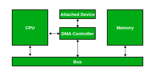
Direct Memory Access (DMA): For high-speed data transfer, the controller uses DMA to transfer data directly to or from memory without constantly involving the CPU. The CPU sets up the DMA controller, which handles the data transfer autonomously, only notifying the CPU when the task is complete.
Polling: Some systems use polling, where the CPU periodically checks the device status register instead of using interrupts. This is simpler but less efficient, especially if the CPU has to wait for the device.
3. Examples of Device Controllers
Disk Controller: Manages operations for storage devices (HDDs, SSDs). It translates CPU commands into read/write actions on the storage device.
Network Interface Card (NIC): Connects a computer to a network and manages network communication.
Graphics Controller: Manages display output, controlling how images are displayed on the screen.
4. Benefits of Device Controllers
Modularity: They allow the CPU to communicate with various types of devices without needing device-specific logic.
Efficiency: By handling low-level tasks independently, they reduce the workload on the CPU.
Standardization: Many device controllers follow standard protocols, ensuring compatibility across different devices.
Direct Memory Access (DMA)
1. Concept:
DMA allows certain hardware subsystems to access main system memory independently of the CPU. This is particularly useful for large data transfers (e.g., reading a file from disk to RAM), as it frees up the CPU for other tasks.
Analogy:
Imagine the CPU is a manager who usually oversees every task. With DMA, it's like the manager hiring an assistant (DMA controller) who can handle routine data transfers directly, without bothering the manager for every small operation. The manager (CPU) only needs to give initial instructions to the assistant (DMA controller), who then completes the task.
DMA is basically about allowing disk drives, external memory, graphic cards, network cards, and sound cards among other devices to read and write data into the memory of the computer. This is achieved without interfering with the operations of the other sections like the CPU.
2. Components Involved in DMA
DMA Controller: This is a dedicated hardware component responsible for managing the data transfer directly between I/O devices and memory.
I/O Device: The hardware (e.g., disk drive, network card) that needs to transfer data to or from memory.
Main Memory: The RAM that stores data for quick access, where DMA operations read from or write to.
3. How DMA Works Step-by-Step
Step 1: Setup – The CPU initiates a DMA transfer by instructing the DMA controller with:
Starting address in memory where the data should be read or written.
Size of the data to transfer (number of bytes).
Direction of the transfer (read from or write to the I/O device).
Step 2: Transfer – Once set up, the DMA controller takes control of the system bus and directly transfers data between the I/O device and memory.
Step 3: CPU-Free Operation – During the transfer, the DMA controller handles the memory and device interaction independently, so the CPU is free to execute other tasks.
Step 4: Completion – Once the transfer is complete, the DMA controller sends an interrupt to the CPU, signaling that the data transfer is finished. The CPU can then process the data if needed.
4. DMA Modes of Transfer
Burst Mode: Transfers a block of data all at once. This is efficient but can temporarily monopolize the system bus, blocking other components from accessing memory.
Cycle Stealing Mode: Transfers data one byte or word at a time. This allows the CPU to interleave its own memory access requests between each DMA transfer, sharing the bus.
Transparent Mode: The DMA controller only transfers data when the CPU is not using the bus. This has minimal impact on CPU performance but may be slower for high-volume transfers.
5. Advantages of DMA
Efficiency: Reduces CPU workload since the CPU doesn’t handle each individual data transfer.
Speed: Enables faster data transfer compared to CPU-managed transfers, especially with high-speed devices.
Concurrent Processing: Allows the CPU to work on other tasks while data transfer is happening, improving overall system performance.
6. Examples of DMA Usage
Disk Drives: Moving large files between memory and storage.
Audio and Video Cards: Streaming data directly from memory to the device without interrupting the CPU.
Network Interface Cards: Quickly loading packets from memory for faster network processing.
7. Limitations of DMA
Bus Contention: Since the DMA controller takes control of the system bus during transfers, it can create delays for other components needing memory access.
Complexity: Setting up and managing DMA transfers adds complexity to system design and requires precise hardware coordination.
Goal of Interrupt Handlers
Interrupt handlers are critical components in operating systems, designed to efficiently handle interruptions (or signals) from hardware or software, notifying the CPU that an event requires immediate attention. They play an essential role in allowing the CPU to respond quickly to various system events, ensuring smooth, efficient operation.
Here’s a breakdown of the Goals of Interrupt Handlers:
1. Minimize Interrupt Latency
Goal: Ensure that interrupts are responded to as quickly as possible.
Explanation: When an interrupt occurs, it signals the CPU to pause its current task and handle a new event. The time taken from the moment the interrupt occurs until the CPU starts executing the interrupt handler is called interrupt latency. Reducing this latency ensures that the system can respond to real-time events, such as keyboard inputs or network packets, promptly.
Example: In a real-time system like a pacemaker, low interrupt latency is critical, as delays in responding to heart signals could have severe consequences.
2. Efficiency in Processing Interrupts
Goal: Process the interrupt quickly without affecting overall system performance.
Explanation: An interrupt handler should do only the necessary tasks and leave other, more complex operations for later stages, often called "deferred processing" or "bottom halves." This keeps the interrupt handler fast, preventing the CPU from being overwhelmed by long-running interrupt tasks.
Example: For a keyboard interrupt, the handler would capture the key press and store it in a buffer. More complex actions (like processing key combinations or updating the display) are deferred to prevent delays.
3. Prioritization and Handling of Multiple Interrupts
Goal: Properly prioritize and manage multiple, simultaneous interrupts.
Explanation: Systems often have many interrupt sources (e.g., disk, network, timers), so interrupt handlers need a mechanism to prioritize which interrupt to handle first. This can prevent important tasks from being delayed by less critical events.
Example: A real-time operating system might prioritize interrupts from a network card (handling high-speed data) over an interrupt from a keyboard, as data transmission requires immediate attention to prevent packet loss.
4. Prevent Data Loss and Ensure Data Consistency
Goal: Avoid losing data and maintain system integrity during interrupt handling.
Explanation: Interrupts often occur because hardware has data ready (e.g., network packets, sensor readings) that needs to be quickly stored or processed. If the interrupt handler is too slow or incorrectly designed, critical data might be lost. Handlers must also ensure data consistency by carefully managing shared resources and avoiding race conditions.
Example: In networking, an interrupt may signal that a packet has arrived. If the handler doesn’t quickly process and store this packet, it may be overwritten by a subsequent packet, leading to data loss.
5. Minimize Interference with Ongoing Tasks
Goal: Minimize the impact of the interrupt on the tasks that were running before the interrupt occurred.
Explanation: Interrupts inevitably disrupt the current CPU task, but good interrupt handling aims to make this disruption as brief as possible. After handling the interrupt, the CPU should be able to return smoothly to its original task without issues.
Example: If a file download is happening and a mouse click interrupt occurs, the interrupt handler should deal with the mouse click quickly, so the CPU can return to managing the download without any noticeable delay.
6. Provide Reliable and Predictable Responses
Goal: Ensure that the system’s response to interrupts is consistent and predictable.
Explanation: In real-time and critical systems, predictability is essential. Interrupt handlers should be designed to respond in a fixed time frame to ensure that real-time tasks are met. This is particularly important in systems with strict timing requirements.
Example: In an automotive system, predictable handling of interrupts from sensors (e.g., brake pressure sensors) is crucial to maintain safe and reliable operation.
7. Facilitate Easy Debugging and Maintenance
Goal: Make interrupt handling code as simple and modular as possible to ease debugging.
Explanation: Interrupt handlers are often complex and close to the hardware, which makes them difficult to debug. Designing them to be simple, with minimal code execution, and logging important details can help with debugging and system maintenance.
Example: A network card interrupt handler could log when it receives data and any errors encountered. This makes it easier to troubleshoot networking issues later.
8. Enable Efficient Use of CPU and System Resources
Goal: Use system resources efficiently, allowing the CPU to focus on other tasks when not handling interrupts.
Explanation: Interrupt handlers should be efficient to avoid using excessive CPU time or resources. By efficiently handling interrupts, the system can remain responsive and allocate resources to user applications and other system functions.
Example: On a mobile device, minimizing CPU usage in interrupt handling can help preserve battery life, as the CPU doesn’t stay engaged in tasks longer than necessary.
Device Drivers
Device drivers are specialized software components that act as an interface between the operating system and hardware devices. Their primary role is to allow the OS to communicate and control hardware without needing to understand the specific details of how each device works. Here’s an in-depth look at device drivers:
Purpose of Device Drivers
Goal: To provide a standard interface for hardware devices to communicate with the operating system.
Explanation: Each hardware device (like a keyboard, printer, or network card) has unique commands and functionalities. The device driver abstracts these specifics, providing a common API that the OS can use regardless of the device's make or model.
Example: The printer driver allows the OS to send print commands without needing to understand how each brand of printer functions internally.
Types of Device Drivers
Device drivers are often categorized based on the type of hardware they control:
Kernel-mode drivers: These drivers run with high privileges, directly accessing hardware and system memory. They are typically used for essential system components like disk controllers and network interfaces.
User-mode drivers: These drivers run in user space with lower privileges, often for devices that don’t require direct memory access (DMA) or low-level hardware control, like USB devices or printers.
Structure and Working of Device Drivers
Device drivers generally have two main components:
Upper Half (or Top Half):
Goal: To handle high-level device interactions initiated by user commands.
Explanation: The upper half typically processes I/O requests from user applications. It translates these requests into hardware instructions for the lower half of the driver to execute.
Example: For a printer, the upper half might receive a print command from an application and prepare it by formatting data.
Lower Half (or Bottom Half):
Goal: To directly manage hardware operations, often at a lower level.
Explanation: The lower half deals with actual hardware communication, such as setting up data transfers or configuring device registers. It may interact with the hardware through commands, register configurations, and data transfer operations.
Example: In the printer driver, the lower half sends the formatted data to the printer hardware, monitors the status of printing, and reports any errors.
Key Functions of Device Drivers
Device drivers are responsible for a range of functions, which can vary based on the type of device. Here are some core tasks:
Initialization and Configuration:
Goal: Set up and configure the device when the system starts or when the device is connected.
Explanation: Drivers must initialize devices to prepare them for use, setting any required parameters and checking for functionality.
Example: The network driver might configure the network card with IP settings during startup.
Data Transfer and Communication:
Goal: Manage data transfers between the OS and the device.
Explanation: Drivers facilitate data transfer by breaking data into manageable packets or by controlling buffers and caches. For fast devices, Direct Memory Access (DMA) may be used for efficient data handling.
Example: The disk driver breaks file read/write requests into smaller blocks and transfers them to/from the disk.
Interrupt Handling:
Goal: Respond to interrupts generated by devices.
Explanation: When a device needs attention (e.g., data ready, task complete), it sends an interrupt signal. The driver’s interrupt handling function processes these signals, taking necessary actions like reading data or restarting transfers.
Example: A keyboard driver handles keypress interrupts, capturing the key data and passing it to the OS.
Error Handling:
Goal: Identify and manage device errors, ensuring system stability.
Explanation: If a device encounters an error (like disk failure or connection loss), the driver must handle it gracefully, reporting the error and attempting to recover.
Example: A storage driver might log a read error and retry the operation, or it could notify the OS of a critical disk failure.
Power Management:
Goal: Manage the device’s power usage to conserve energy.
Explanation: Drivers can reduce power consumption by putting devices into low-power or standby modes when not in use, which is particularly useful for battery-operated devices.
Example: A graphics driver might lower GPU power consumption when not actively rendering graphics.
Device Removal and Hot Swapping:
Goal: Safely handle the disconnection or removal of devices.
Explanation: For plug-and-play or hot-swappable devices (like USBs), drivers must manage proper shutdown and cleanup of resources if the device is removed.
Example: When a USB drive is removed, the USB driver ensures all files are safely saved and resources freed before final removal.
Benefits of Device Drivers
Hardware Abstraction: Allows the OS to operate with different devices without needing specialized code for each hardware type.
Modularity: Separates hardware-specific code from the OS kernel, making it easier to add or update devices.
Error Isolation: Errors within a driver often don’t affect the core OS, helping to maintain stability and security.
Challenges with Device Drivers
Compatibility: Drivers need to be compatible with both the hardware and the OS. Older drivers may not work with newer OS versions and vice versa.
Complexity and Debugging: Drivers require intricate coding and can be hard to debug, as they directly interact with hardware.
Security: Drivers with kernel access can be a target for malicious attacks, so they must be carefully written to avoid vulnerabilities.
Device Independent I/O Software
Concept:
Device-Independent I/O software is an abstraction layer in the operating system that provides a common interface for performing I/O operations, regardless of the specific characteristics of individual devices. This layer ensures that the OS can manage I/O tasks in a consistent way without needing to know the specifics of each hardware device.
Purpose of Device-Independent I/O Software
Goal: To provide a uniform, consistent way for the operating system to interact with various devices without depending on device-specific details.
Explanation: This layer allows applications and the OS to execute I/O operations (like reading from or writing to a file) using the same functions, regardless of whether the operation is targeting a disk, a network card, or a keyboard.
Example: When an application requests a file read operation, it doesn’t need to know if the file is stored on an SSD, HDD, or a network drive. The device-independent I/O software handles these details.
Key Functions of Device-Independent I/O Software
Device-independent I/O software performs several crucial tasks:
Naming and File System Abstraction:
Goal: To provide a uniform naming convention for files and devices.
Explanation: Device-independent I/O assigns each device or file a unique name and enables access to it through a standard naming structure, such as a file path. This abstraction hides the underlying device specifics, so users and applications access devices in the same way they access files.
Example: A user accesses "C:\file.txt" or "/dev/sda1" regardless of the underlying physical storage device.
Buffering:
Goal: To store data temporarily to improve performance and handle different device speeds.
Explanation: Buffering smooths out the differences in speed between fast CPUs and slower I/O devices. It temporarily stores data in memory before it’s sent to or received from a device, ensuring smoother and more efficient I/O operations.
Example: When writing a large file to a disk, the data is buffered in memory before it’s written in chunks to the disk, rather than trying to write it byte-by-byte.
Caching:
Goal: To retain frequently accessed data in memory for faster access.
Explanation: Caching stores copies of data that is likely to be accessed multiple times, reducing the need to read from or write to slower devices. This improves performance by reducing the number of actual I/O operations.
Example: A disk cache may store recently accessed files in memory, so if the user needs the same files again, they can be accessed much faster.
Error Reporting:
Goal: To detect and report errors to the OS in a standardized way.
Explanation: Device-independent I/O software manages error messages for various devices and presents them in a consistent format. This helps the OS and applications understand and respond to device errors more effectively.
Example: When a read operation fails due to a disk error, the device-independent I/O software sends a standardized error message to the OS.
Device Allocation and Protection:
Goal: To manage device access and prevent unauthorized use.
Explanation: Device-independent I/O software controls which processes can access certain devices, preventing conflicts and ensuring security. It uses permissions and access control mechanisms to allocate devices safely.
Example: If two programs try to write to a printer simultaneously, the software allocates access to one process at a time or queues the requests to avoid conflicts.
Device-Independent Block Size:
Goal: To manage data transfer in a consistent block size across devices.
Explanation: Devices can have different block sizes (e.g., disks with 4KB blocks vs. 512-byte sectors). The OS standardizes the block size at the device-independent layer, so applications can read/write in uniform blocks.
Example: Regardless of the disk type, a file read operation can be standardized to retrieve data in 4KB blocks for simplicity.
Uniform Device I/O Interface:
Goal: To provide a standard set of system calls for I/O operations.
Explanation: This interface allows applications to perform I/O actions without device-specific system calls, using a common set of operations like open(), read(), write(), and close().
Example: The open() system call is the same whether opening a file on a disk or a network socket.
Advantages of Device-Independent I/O Software
Ease of Development: Programmers don’t need to write device-specific code since a uniform interface handles I/O tasks.
Portability: Applications can operate on different hardware with minimal changes, as they interact with the OS using standardized calls.
Modularity: Device-independent I/O separates high-level I/O logic from hardware-specific details, simplifying maintenance and updates.
Example Scenario
Imagine you’re watching a video that is stored on an external hard drive. As the video player reads the file, here’s how device-independent I/O software comes into play:
File Naming: The video file is accessed through a path like E:\movies\video.mp4, and the OS does not need to know whether E: is an HDD or SSD.
Buffering: The video data is buffered in memory, allowing the player to read ahead smoothly and avoid stuttering if there’s a slight delay in the drive’s response.
Caching: The most recently accessed parts of the video are cached, so if you replay a scene, it loads instantly from memory rather than re-reading from the drive.
Error Handling: If the drive encounters an issue, a standard error is reported, allowing the video player to gracefully handle it, such as pausing or showing an error message.
Uniform Interface: The player uses standard read operations, unaware of whether the file resides on an external hard drive or network storage.
This abstraction of I/O functions ensures smoother interactions with diverse devices and enhances overall system stability and performance.
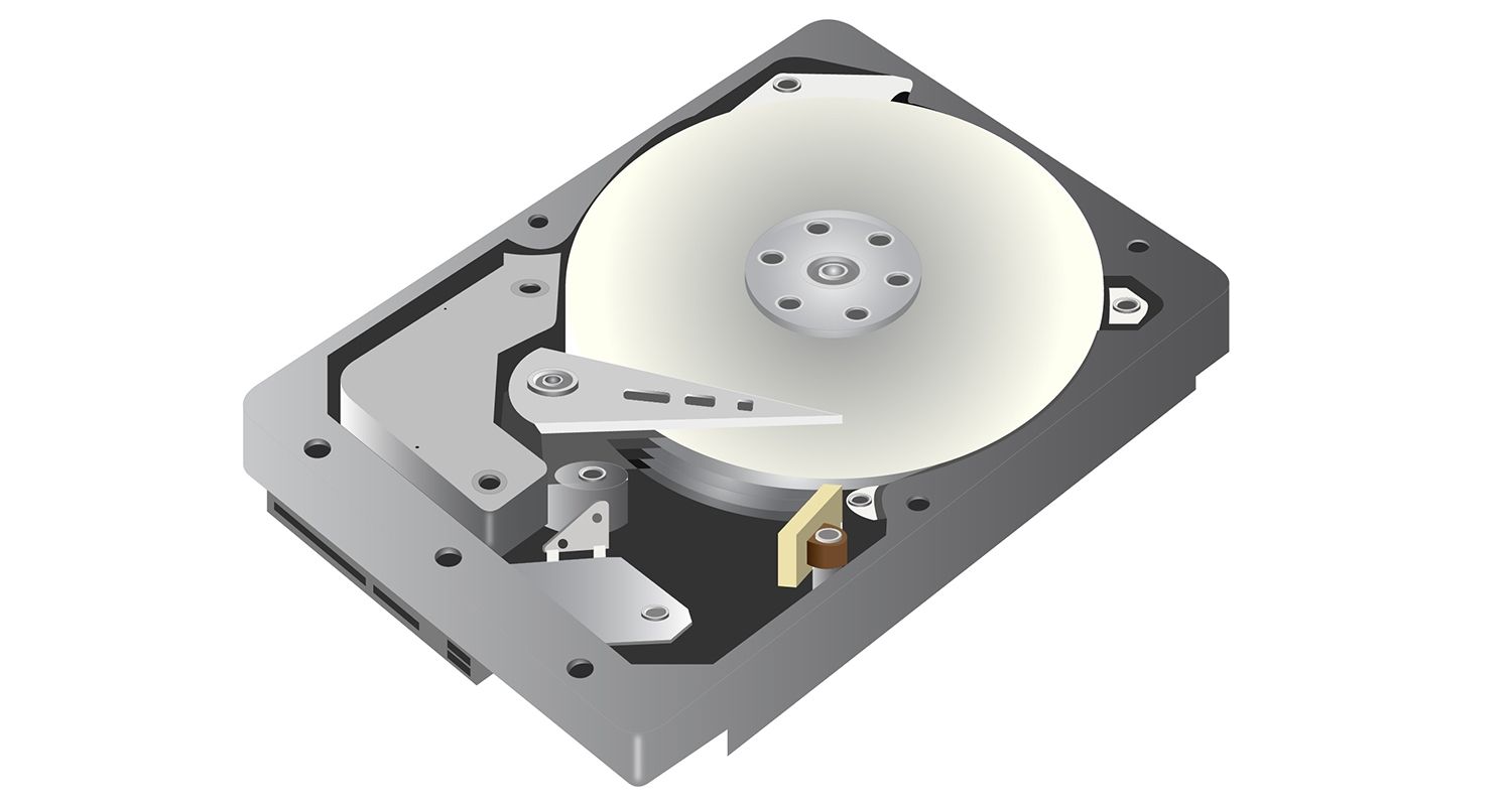
Disk Architecture
Here we will study the architecture of a Hard Disk (HDD). Y'know, the old cranky ones, with rotating platters.
Yeah, this one.
Here is a very good theoretical explanation as how to how an HDD works, in detail.
You can either visit the website to view the content or just read here, since I just copied the content from there.
A hard disk drive (HDD) is an internal or external computer component that stores data, such as the operating system, applications, and user files.
HDDs are “non-volatile” storage devices, meaning they retain stored data even when power isn't being supplied.
How does a hard drive work?
An HDD includes two main elements; a spinning platter and an actuator arm.
The platter is a circular magnetic disk containing tracks and sectors that retain data.
The actuator arm moves across the platter to read and write data.
The platter spins (hence the name) on a spindle to help speed up the read/write process as the actuator arm moves across it.
The data sectors are spread out randomly (also known as fragmented) across the platter, and below we'll discuss defragmenting a hard drive to boost performance.
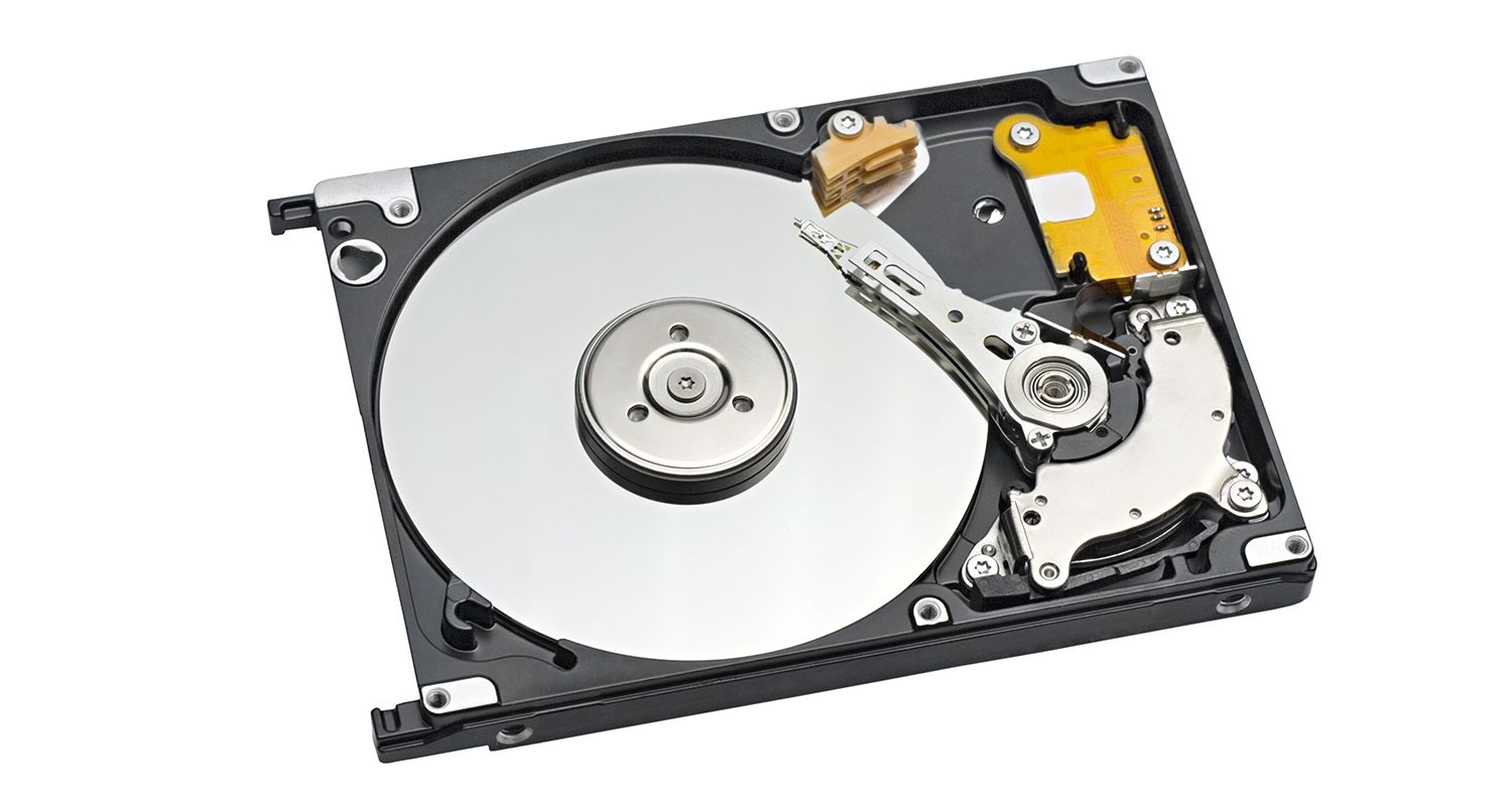
What does a hard disk drive look like?
The platter and the actuator arm are delicate physical mechanisms, so a solid case covers them to prevent damage under normal use. The hard drive cover will look like a metal box, and it will be clearly labeled as a hard disk drive or HDD.
Here's what an internal HDD looks like beneath its metal casing. You can see the spinning platter and the actuator arm, and how they work together to read and write the data upon request.
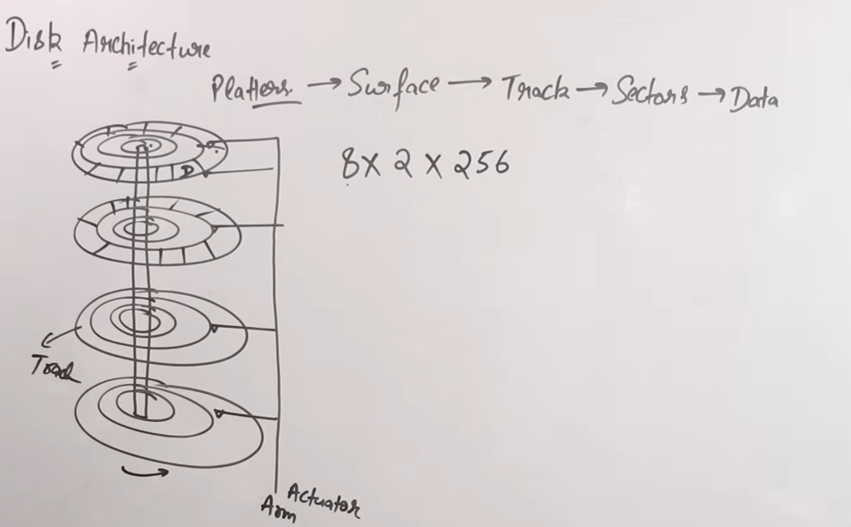
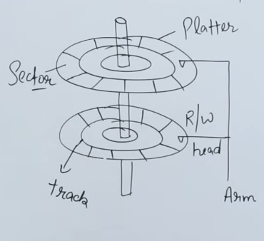
Now here is more diagrammatic side view explanation from this video here :
This is more better detailed algorithm than the previous one.
So as we know, the HDD is made of a series of platters, each platter has a read/write head connected to a long actuator arm.
The read/write heads can be moved inwards or outwards by the actuator arm to either access the inner tracks or the outer tracks.
Some disks use only one surface of the platters while some use both.
Now each platter has a series of tracks on which the read/write head runs and reads data or writes to it. All platters move in the same direction, are clockwise or counter-clockwise. Platters don't move in directions against each other.
Each track has sectors which house the real data. There can be many sectors per tracks.
Now let's say in a question we are asked to find the size of a hard disk (HDD).
We are given the following data :
Number of platters = 8 Number of tracks = 256 Number of sectors = 512 Amount of data per sector = 512 KB.
So in order to find the total size of the disk, we need to multiply all the values, all in the powers of 2.