Module 2 -- Optics -- Physics
Index
- Fraunhofer and Fresnel Diffraction
- What is Light?
- Hyugens' Principle -- How waves propagate
- Pre-requisite to understanding Hyugens' Principle
- What is a Wavelet?
- What is Refraction?
- Laws of Refraction of Light
- What is a Wavefront?
- Definition of Hyugens' Principle
- Diffraction -- How Hyugens' Principle explains it.
- Interference
- The Principle of Superposition
- Two Types of Interference
- How Interference creates Diffraction Patterns.
- Single Slit Diffraction -- The Interference Story
- Double Slit - Pure Interference
- Multiple Slits - Enhanced Interference
- Diffraction Grating
- Polarization of Light
- Polarization by Reflection
- Polarization by Reflection
- Polarization by Scattering
- Circular Polarization
- Two Types of Circular Polarization
- Elliptical Polarization
- Optical Activity
- Why Does Optical Activity Occur?
- Common Optically Active Substances
- Laser
- Pre-requisites to understanding how LASER works.
- Population Inversion - The Heart of Laser Action
- Pumping -- achieving population inversion
- Types of pumping systems in laser
- Two-level pumping in lasers.
- Three-Level pumping Laser System
- Four-Level pumping laser system
- Threshold Population Inversion
Fraunhofer and Fresnel Diffraction
I am assuming, that, like myself, you are also out of touch with physics, for quite a long time, so, let's build from the ground up, brick-by-brick.
What is Light?
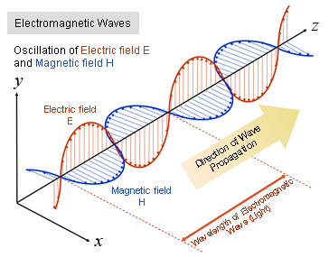
Light is a form of electromagnetic radiation - energy that travels through space as oscillating electric and magnetic fields. Think of it as waves in invisible fields, similar to how water waves travel across a pond's surface. Unlike sound waves which need air to travel, electromagnetic waves can travel through empty space (vacuum) at a constant speed of
Light consists of perpendicular electric and magnetic field oscillations that are also perpendicular to the direction the wave travels. This creates a self-propagating wave that carries energy through space.
The Properties of a Wave
Every wave, including light, has five fundamental properties that completely describe its behavior :
- Wavelength (
): The distance between two identical points on consecutive waves (like crest to
crest or trough to trough). For visible light, wavelengths range from about 400-700 nanometers
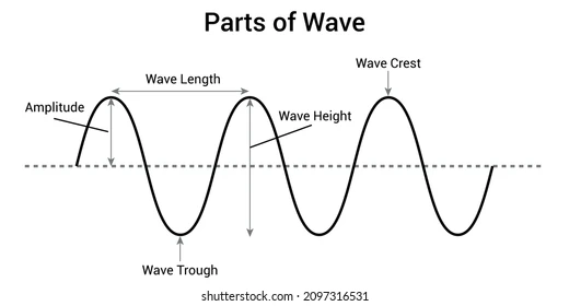
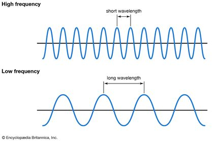
- Frequency (ν or f): The number of complete wave cycles passing a point per second, measured in Hertz (Hz). Higher frequency means more waves pass by each second.
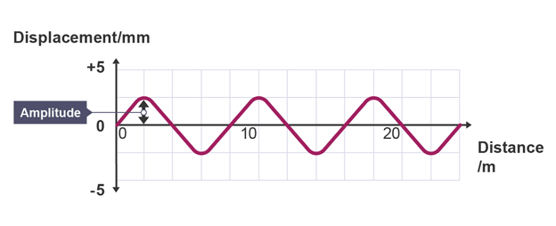
- Amplitude(A): The maximum displacement from the wave's center line to its peak. For light waves, amplitude determines the intensity or brightness.
- Period (T): The time it takes for one complete wave cycle, measured in seconds. Period and frequency are reciprocals:
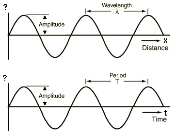
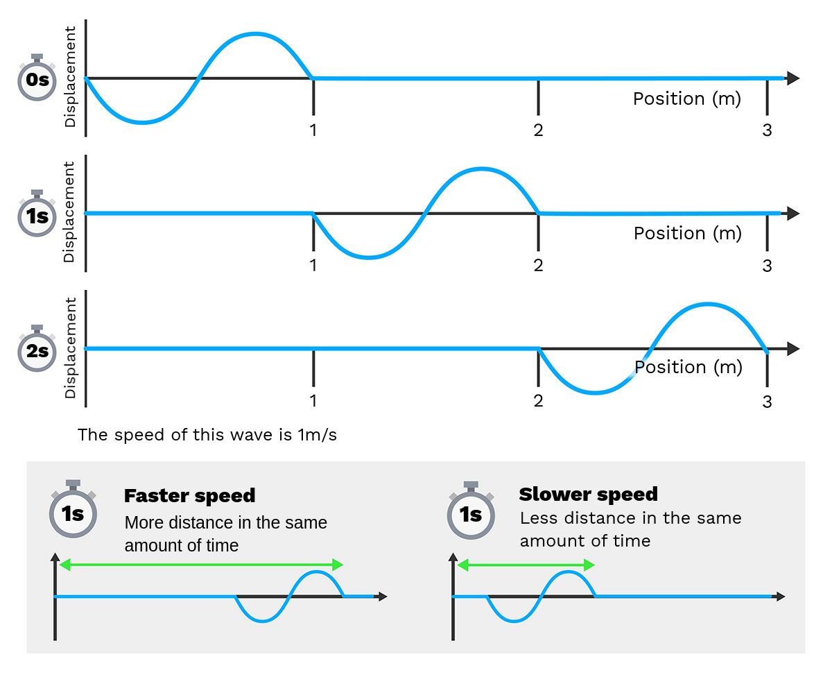
- Wave Speed (v): How fast the wave travels, given by the fundamental wave equation:
. For light in vacuum, this speed is always:
The key relationship is that frequency and wavelength are inversely related - when frequency increases, wavelength decreases, and vice versa, since their product must always equal the speed of light.
Hyugens' Principle -- How waves propagate
Pre-requisite to understanding Hyugens' Principle
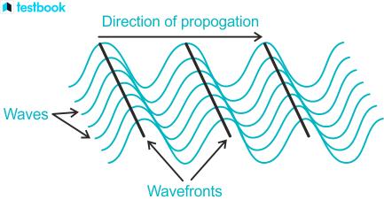
What is a Wavefront?
A wavefront is an imaginary surface connecting all points in a wave that are vibrating in the same phase at the same instant in time. Think of it as a "snapshot" of where all the wave crests (or troughs) are at one moment.
What is a Wavelet?
A wavelet in Huygens' principle is a small, secondary spherical wave that emanates from each point on the primary wavefront. These are not the same as mathematical wavelets used in signal processing - these are physical secondary waves.
What is Refraction?
Refraction is the bending of waves when they pass from one medium to another where they travel at different speeds. For example, light bends when going from air into water because light travels slower in water than in air. Huygens' principle explains this: when part of a wavefront enters the slower medium first, those wavelets slow down while the rest are still moving faster, causing the overall wavefront to bend.
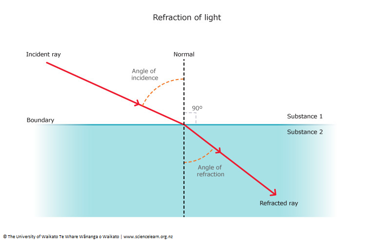
Laws of Refraction of Light
The laws of refraction of light are:
-
The incident ray, the refracted ray, and the normal to the interface between the two media at the point of incidence all lie in the same plane.
-
The ratio of the sine of the angle of incidence to the sine of the angle of refraction is a constant for a given pair of media and is known as the refractive index (Snell's Law)
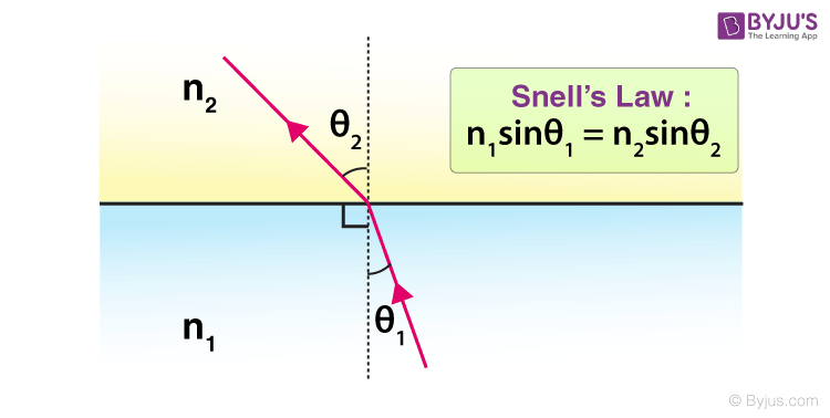
It is given as:
where:
: The refractive index of the first medium. : The refractive index of the second medium. : Angle of incidence : The angle between the incident ray (the ray falling on the surface) and the normal (an imaginary line perpendicular to the surface, extending from the point of incidence, on the surface, out to both mediums). : Angle of refraction: The angle between the normal and the refracted light ray.
Definition of Hyugens' Principle
https://www.youtube.com/watch?v=ANsHXbIoA6U (must watch)
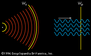
To understand diffraction and interference, you must first grasp Huygens' Principle, proposed by Dutch physicist Christiaan Huygens in 1678.
Huygens' Principle states: Every point on a wavefront acts as a source of secondary spherical wavelets that spread out in all directions at the same speed as the original wave. The new wavefront at any later time is the envelope (common tangent) of all these secondary wavelets.
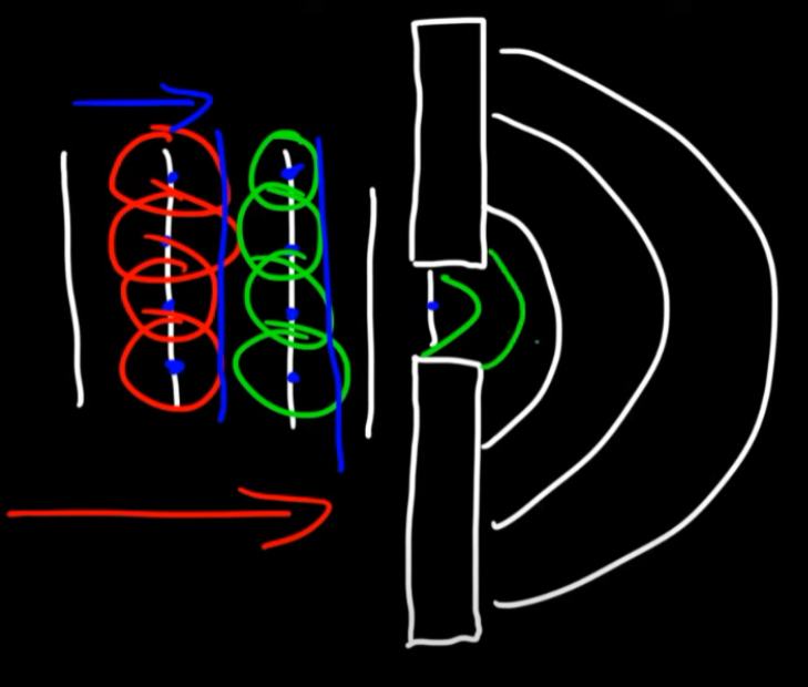
As denoted by the circles, each point on the a wavefront (the straight lines) emits small waves, called wavefronts, which in turn on interacting with each other, create more wavelets and so on...
The second half of the image shows diffraction, which I will get to in the upcoming sections.
These wavefronts are not seen in real life, but imagined by drawing an imaginary line in such a way that it covers all the intersecting points of the waves.
As you can see in this image, the wavefront is created through all the intersections of the existing wavelets, and on that wavefront, even more wavelets are created.
A more better example view of Hyugens' principle would be this image right here:

In this image, one can assume that the starting ripple is the one where we can see some water being displaced and rising above, presumably after having a rock thrown into, we will consider that the source wavefront. The ripple created by that impact, created a wavefront, which in turn created small other wavelets, or other small ripples as seen in the picture, which in turn create more individual wavefronts and create more wavelets, or ripples.
If you look closely enough there is a particular direction to which these ripples are headed, which awfully looks very similar to a diffraction as in the previous image, but best not make that connection now just yet.
Diffraction -- How Hyugens' Principle explains it.
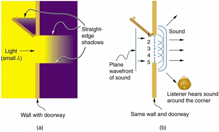
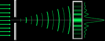
Diffraction is the bending of waves around obstacles or through openings. Here's how Huygens' principle makes this crystal clear:
When a wave encounters an obstacle or opening, only certain points on the wavefront can continue forward - those that aren't blocked. According to Huygens' principle, each of these unblocked points becomes a source of secondary wavelets spreading out in all directions.
Think of it this way: imagine you have a line of people (the wavefront) walking forward together. Suddenly, a wall with a small doorway blocks their path. Only the people near the doorway can pass through. Once through, each person starts spreading out in multiple directions rather than just walking straight ahead.
Single Slit Diffraction Example
When light passes through a narrow slit (an opening with not enough width for the whole wave to pass through), here's what happens step by step:
- The incident wavefront hits the slit - most of it is blocked by the material around the slit.
- Only the portion of the wavefront within the slit opening can continue
- Each point within this slit opening acts as a source of secondary wavelets according to Huygens' principle
- These wavelets spread out in all directions - not just straight forward
- The wavelets interfere with each other, creating bright and dark regions (interference pattern)
Why This Causes "Bending"
The key insight is that waves don't just travel straight through openings. The secondary wavelets spread out in semicircular patterns from each point in the opening. This spreading causes the wave to "bend" around the edges of the opening and spread into regions that would be in shadow if light traveled only in straight lines.
The Sound Analogy
You've actually experienced this many times with sound waves! When someone calls to you from another room with the door open, you can hear them even when you're not directly in front of the doorway. The sound waves don't just shoot straight through the opening - they spread out in all directions due to diffraction, which is why you hear the sound even when standing to the side.
Key Conditions for Observable Diffraction
Diffraction is most noticeable when the opening size is comparable to the wavelength of the wave. For visible light (wavelength ~500 nanometers), diffraction becomes obvious with very small slits. For sound waves (wavelength ~1 meter), diffraction is easily observed with doorways and windows.
Interference
Interference is what happens when two or more waves meet each other in the same medium. When waves overlap, they don't bounce off each other like colliding balls - instead, their effects combine according to the principle of superposition.
The Principle of Superposition
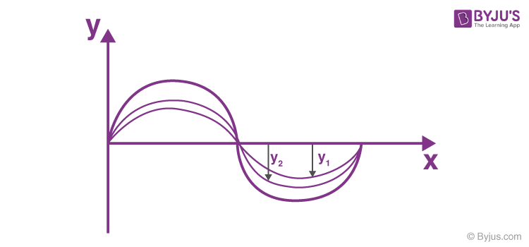
The interference principle is explained by the superposition principle, which states that when two or more waves overlap, the total displacement at any point is the algebraic sum of the individual wave displacements. This combination results in two types of interference: constructive interference, where waves in the same phase reinforce each other to create a larger amplitude, and destructive interference, where waves in opposite phases cancel each other out to create a smaller or zero amplitude.
Think of it like this: if one wave pushes a water particle up by 2 units and another wave pushes the same particle up by 3 units at the same instant, the particle moves up by 2 + 3 = 5 units total.
Two Types of Interference
https://www.youtube.com/watch?v=JBuW385IT38 (must watch)
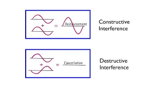
Constructive Interference
This occurs when waves reinforce each other :
- Crest meets crest (both waves pushing up together)
- Trough meets trough (both waves pulling down together)
- The waves are said to be **"in phase"**
- Result: Larger amplitude - brighter light, louder sound, higher water waves
Destructive Interference
This occurs when waves cancel each other out :
- Crest meets trough (one pushes up while other pulls down)
- The waves are "out of phase" by half a wavelength
- Result: Reduced or zero amplitude - dimmer light, quieter sound, flatter water
- If the waves have equal amplitude, they can completely cancel each other!
Real-World Examples You've Experienced
Water Waves: Drop two pebbles into a pond simultaneously. Where the ripples from each pebble meet, you'll see some areas with bigger waves (constructive interference) and some areas that are relatively calm (destructive interference).
Sound Waves: When you hear "beats" in music - that wobbling sound when two slightly different notes are played together - that's interference. The sound gets louder and softer in a regular pattern as the waves go in and out of phase.
Noise-Canceling Headphones: These work by creating sound waves that are exactly out of phase with unwanted noise, causing destructive interference that cancels the noise.
Key Requirements for Clear Interference
For interference patterns to be easily observable, the waves must be coherent.
Coherent Waves
Coherent waves have the same frequency and a constant phase difference between them. This means the waves maintain a consistent relationship in their oscillations over time, allowing them to interfere in a stationary way to produce interference patterns.
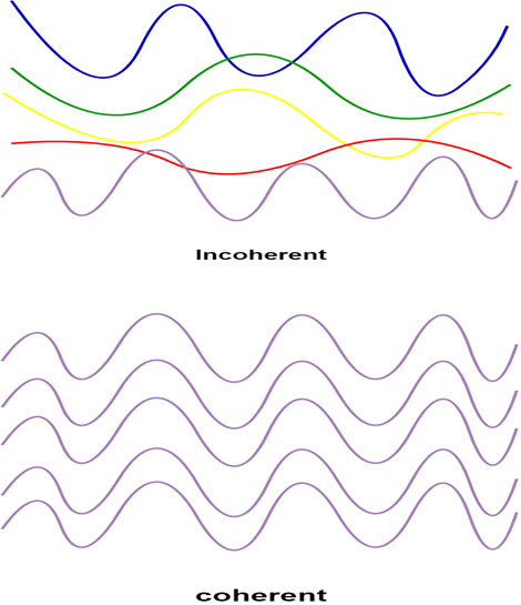
- Same frequency (or very close frequencies).
- Constant phase relationship between the sources.
- Similar amplitudes work best.
Random sources (like two separate light bulbs) don't create stable interference patterns because their phase relationship constantly changes randomly.
Mathematical Description
If two waves have displacements
This simple addition can create complex, beautiful patterns when extended over space and time.
How Interference creates Diffraction Patterns.
When I mentioned diffraction earlier, I mentioned that the secondary wavelets from different points in an opening interfere with each other to create bright and dark regions. Now that we understand interference, let's see exactly how this works.
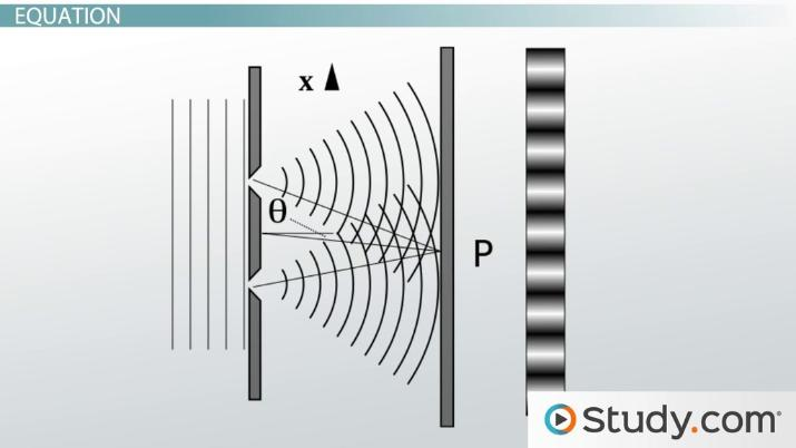
Single Slit Diffraction -- The Interference Story
When light passes through a single slit :
-
Every point across the slit width creates secondary wavelets. (Since the light waves are oscillating, the reduced space created by the slit, causes only select parts of the existing waves pass through and collide with each other (one can imagine the gap in the slit as a wavefront) and cause secondary wavelets, which then collide with each other and create more wavelets, this happens till the interference patterns caused by the collisions are observed on the screen.)
-
These wavelets travel in all directions - not just straight forward
-
At any point on the screen, wavelets from different parts of the slit arrive with different path lengths
-
Different path lengths mean different phases
-
Wavelets interfere constructively (bright) or destructively (dark) based on their phase relationships
The Path Difference Concept
This is crucial: wavelets traveling to the same point on the screen from different parts of the slit travel different distances. This path difference determines whether they arrive in phase (constructive interference) or out of phase (destructive interference).
For destructive interference (dark fringes), the condition is: path difference = mλ where m = 1, 2, 3... and λ is wavelength.
For a single slit of width a, this translates to: a sin θ = mλ for dark fringes.
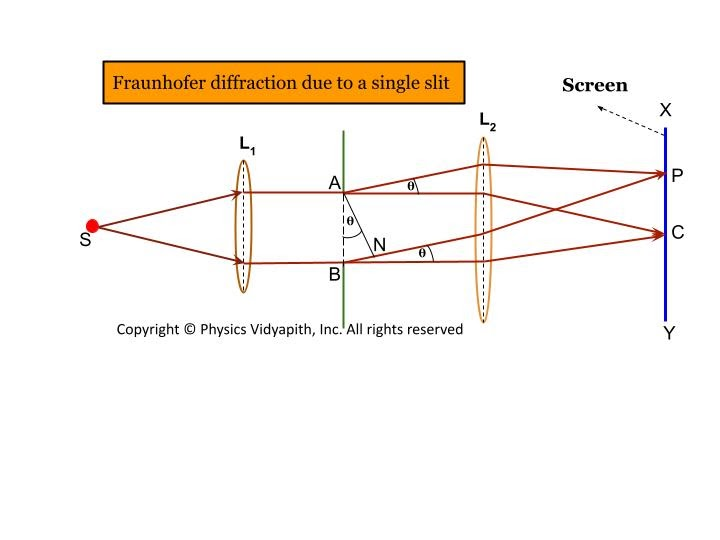
Double Slit - Pure Interference
In double slit experiments :
-
Each slit behaves like its own single slit(in each separate slit, the same behaviour of light is observed): light passes through, and each point in the opening acts as a source of secondary wavelets (following Huygens’ principle), generating a diffraction pattern from each slit.
-
The crucial addition: the light from the two slits creates two separate coherent sources.
-
The waves emerging from each slit then interfere with each other on the screen, leading to a complex pattern of bright and dark bands (maxima and minima).
-
This overall pattern is a combination of diffraction (from each slit) and interference (between the two slits as distinct sources).
-
Bright fringes where:
(where d = slit separation) -
Dark fringes where:
The Key Insight
Diffraction patterns ARE interference patterns! The difference is just in what's interfering
:
- Interference: Waves from separate sources interfering
- Diffraction: Different parts of the same wavefront interfering after passing through openings or around obstacles
Both follow the same superposition principle you learned - waves add up where they're in phase (bright) and cancel where they're out of phase (dark).
Multiple Slits - Enhanced Interference
With diffraction gratings (many parallel slits) :
-
Many sources of coherent light interfere
-
Much sharper and brighter patterns because more waves reinforce at specific angles
-
Same basic physics: path difference determines constructive vs destructive interference
-
Bright fringes: d sin θ = mλ (same as double slit, but much sharper!)
The beauty is that whether it's 2 slits, 1000 slits, or even a single slit creating wavelets across its width, the fundamental mechanism is always interference of coherent waves!
Fraunhofer and Fresnel Diffractions -- The difference
Fraunhofer and Fresnel diffraction are the two main categories of diffraction that describe how light behaves when it encounters obstacles or openings, but they model very different physical setups.
Fraunhofer Diffraction
-
Fraunhofer diffraction is also known as “far-field diffraction.”
-
It occurs when both the light source and the screen (where you observe the pattern) are effectively at infinite distance from the obstacle or slit. In practice, this is achieved using lenses to make the incoming light rays parallel (plane wave) and to focus the outgoing rays onto a screen.
-
In Fraunhofer diffraction, the analysis is simpler because the incoming and outgoing waves can all be treated as straight, parallel rays.
-
Patterns are sharp and easy to analyze mathematically, which is why this is the most commonly studied case in textbooks and laboratory experiments.
-
Example: Most single-slit, double-slit, and grating experiments performed with lasers and lenses are Fraunhofer setups.
Typical Setup:
- Parallel light (from a distant source or with a collimating lens) passes through a slit.
- A converging lens focuses rays onto a screen.
- The resulting pattern is due to the interference of secondary wavelets from the slit.
Fresnel Diffraction
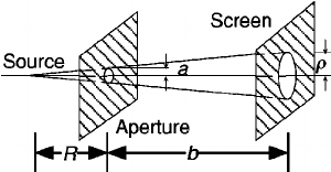
- Fresnel diffraction is also called “near-field diffraction.”
- It happens when **either the light source or the screen or both are at a finite (closer) distance to the slit or obstacle**.
- Here, wavefronts are spherical or cylindrical, not plane waves as in Fraunhofer.
- The geometry is more complex, so calculations are less straightforward.
- The pattern you see changes as you move the screen—characteristic of near-field effects.
Typical Setup:
- No lenses used to create parallel light or to focus the pattern.
- The observed pattern depends on the distance between the slit/obstacle and the screen.
- Used to observe effects like the edge diffraction shadow pattern or bright/dark zones near an obstacle.
What do They Describe?
Both types of diffraction describe how light bends and creates patterns of light and dark (or colored) bands after passing through slits/edges. The main difference is the geometry of how the light reaches the obstacle and the screen:
- Fraunhofer: Parallel incoming and outgoing rays (requires lenses or large distances)
- Fresnel: Curved (spherical) incoming/outgoing wavefronts; closer screen or source; pattern changes with distance.
Diffraction Grating
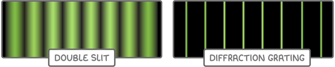
A diffraction grating is an optical element made up of a large number of closely spaced, parallel slits or grooves—typically hundreds or thousands per millimeter. When a beam of light passes through (or reflects off) the grating, each slit or groove acts as a source of secondary wavelets according to Huygens’ principle. These wavelets then spread out and interfere with each other, creating a series of sharp, well-defined light and dark bands (interference maxima and minima) at specific angles.
However, as one would expect that using more slits would result in more complex interference patterns, this is not the case:
Why Sharper, Not More Complex?
With just two slits, you get many evenly-spaced bright and dark fringes spread across the screen. But with a diffraction grating (many slits):
- The bright maxima become extremely sharp and intense because waves from hundreds of slits all reinforce at very precise angles.
- The dark regions between maxima become much wider and darker.
- Fewer bright fringes are visible because they're separated by much larger angles.
- The pattern consists of very bright, narrow lines separated by large dark regions, rather than many closely-spaced fringes
Principle and Formula
- Incoming light hits the grating.
- Each slit diffracts the light, and the diffracted waves interfere.
- The grating equation describes where the bright fringes (constructive maxima) appear:
What Do the Symbols Mean?
-
a: This is the width of the single slit. It's the distance from one edge of the slit to the other—essentially, how "wide" the opening is through which the light passes.
-
θ (theta): This is the angle measured from the central axis (directly in front of the slit) to the direction where a dark fringe (minimum) appears on the screen.
-
m: This is the order number of the minimum (m = 1 for the first minimum, m = 2 for the second, etc.; m is an integer, but not zero for minima).
-
λ (lambda): This is the wavelength of the light being used.
Key Points
-
Each order m corresponds to a specific color (wavelength) and angle.
-
The 0th order (m = 0) is the central bright spot, where all wavelengths reinforce straight ahead.
-
Bright maxima at other orders (
) spread outward, with each wavelength at a distinct angle, so the grating separates “white” light into its color components. -
More slits = sharper, brighter maxima and better resolution, since waves from hundreds or thousands of sources reinforce only at precise angles.
Applications
- Spectroscopy: Separating and measuring different wavelengths (colors) in light.
- Monochromators: Selecting one wavelength from a spectrum.
- Optical instruments: Improving angular resolution and analyzing complex light sources.
Polarization of Light
What Is Polarization of Light?
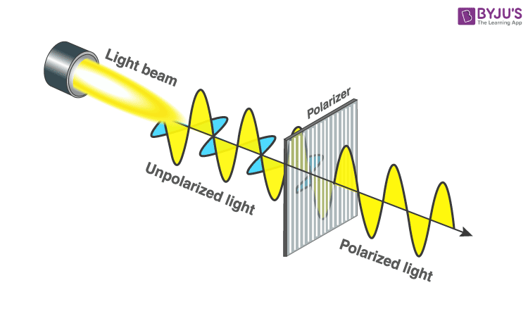
Polarization describes the orientation of the oscillations of the electric field in a transverse wave such as light.
Light, being an electromagnetic wave, is made up of oscillating electric and magnetic fields. These oscillations are perpendicular to each other and to the direction in which the light wave is traveling. However, the direction in which the electric field vibrates can vary:
-
Unpolarized light: The electric field oscillates randomly in all perpendicular directions to the direction of travel. Natural sunlight, light from most lamps, and LED or bulb light are unpolarized, meaning at any instant, the electric field could be pointing in any plane perpendicular to the light’s path.
-
Polarized light: The oscillations of the electric field are restricted to one specific direction (or plane) perpendicular to the direction of propagation. All the electric field vectors vibrate in the same direction as the light travels forward. This is sometimes called "plane" or "linear" polarization.
Visual Analogy
-
Imagine a rope being shaken up and down—if the wave travels horizontally and only goes up and down, that’s linearly (plane) polarized light.
-
In contrast, if the rope is shaken randomly in every direction as the wave moves forward, that’s unpolarized light.
Why Does This Matter?
Polarization is a distinguishing feature of transverse waves (not longitudinal, like sound in air).
Polarized light is crucial in many areas of physics and technology—such as in Polaroid sunglasses (reduce glare by blocking certain polarizations), photography, LCD screens, and optical experiments.
Polarization by Reflection
When unpolarized light strikes the boundary between two transparent media (like air and glass, or air and water), part of the light is reflected and part is refracted. The key discovery is that the ==reflected light becomes partially or completely polarized==, depending on the angle of incidence.
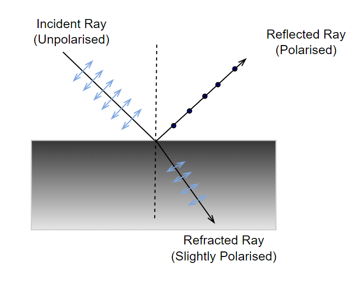
The Basic Phenomenon
When unpolarized light reflects off a surface:
-
Light with electric field vibrations perpendicular to the plane of incidence (called s-polarized light) is preferentially reflected.
-
Light with electric field vibrations parallel to the plane of incidence (called p-polarized light) is preferentially refracted (transmitted) into the second medium.
The plane of incidence is the plane containing the incident ray, reflected ray, and the normal (perpendicular) to the surface.
Brewster's Angle (Polarizing Angle)
At a special angle of incidence, called Brewster's angle
At Brewster's angle:
- The reflected ray and refracted ray are perpendicular to each other (they make a 90° angle)
- The reflected light contains only s-polarized light (vibrations perpendicular to the plane of incidence)
- No p-polarized light is reflected at all
Brewster's Law
Brewster's Law mathematically describes the polarizing angle:
Or, if light is traveling from air (
Where:
= Brewster's angle (angle of incidence for complete polarization) = refractive index of the first medium (incident medium) = refractive index of the second medium (reflecting surface)
Polarization by double reflection
Polarization by double reflection involves passing unpolarized light through two reflecting surfaces (often glass plates) set at specific angles. Here’s what happens:
-
When unpolarized light reflects off a surface, like glass, at Brewster’s angle, the reflected light is partially or fully polarized (as discussed previously).
-
If this partially polarized reflected light then reflects off a second surface, especially if the second surface is also set at Brewster’s angle relative to the first, the light emerging becomes even more strongly polarized.
-
With each successive reflection under the right conditions, the degree of polarization increases, eventually leading to light that is almost completely plane-polarized.
How It Works
-
First Reflection: Some unpolarized light is polarized upon reflecting off the first plate.
-
Second Reflection: The already partially polarized light hits a second plate. The component of light already polarized parallel to the incident plane is further reduced (as reflection at Brewster’s angle favors polarization perpendicular to the plane). This means the light becomes even more exclusively polarized in the direction perpendicular to the incidence plane.
Practical Demonstrations
-
Pile of Plates: One classic experiment involves passing light through a "pile" of many thin glass plates, all set at or near Brewster’s angle. Each plate enhances the polarization effect, and the light emerging is almost completely polarized.
-
This principle is used in optical devices for generating highly polarized light needed in scientific experiments and equipment, such as in some types of polarizers and laser technologies.
Key Point
- Double (or multiple) reflection is an efficient way to obtain highly polarized light from an initially unpolarized source—especially when using plates set at Brewster’s angle.
Polarization by Scattering
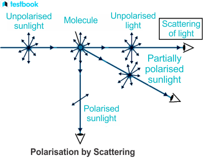
Scattering occurs when light encounters small particles (like air molecules, dust, or water droplets) and gets redirected in various directions. One of the beautiful consequences of scattering is that the scattered light can become polarized, even though the incident light is unpolarized.
The Phenomenon
When unpolarized sunlight passes through Earth's atmosphere, it collides with air molecules (nitrogen and oxygen primarily). These molecules scatter the light in different directions.
Key observation: The scattered light observed at 90° to the direction of the incident sunlight is completely plane-polarized.
Why Does This Happen?
Here's the physical mechanism:
-
Unpolarized sunlight strikes an air molecule.
-
The oscillating electric field of the light causes the electrons in the molecule to oscillate in all directions perpendicular to the light's travel direction.
-
These oscillating electrons act like tiny antennas, re-radiating (scattering) light in various directions.
-
However, dipole oscillations do not radiate along their axis of oscillation.
-
Therefore, when observing scattered light at 90° to the incident beam, you only see light from oscillations perpendicular to both the incident direction and your line of sight.
-
This means the scattered light at 90° is completely polarized.
Real-World Example: The Sky
This is exactly why the sky appears blue and is polarized!
-
When you look at the sky at an angle perpendicular to the sun's rays (about 90° from the sun), the scattered sunlight is strongly polarized.
-
This is why polarizing sunglasses work so well outdoors—they block the polarized scattered light, reducing glare and making the sky appear darker and clearer.
-
Photographers use polarizing filters to enhance blue skies and reduce atmospheric haze.
Degree of Polarization
- At 90° to the incident beam: Maximum polarization (nearly 100%)
- At other angles: Partial polarization
- At 0° or 180° (forward or backward scattering): No polarization
Applications
-
Photography: Polarizing filters enhance contrast in sky photos
-
Navigation: Some animals (like bees) can detect polarized skylight for navigation[
-
Remote sensing: Understanding atmospheric scattering and polarization helps in satellite imaging
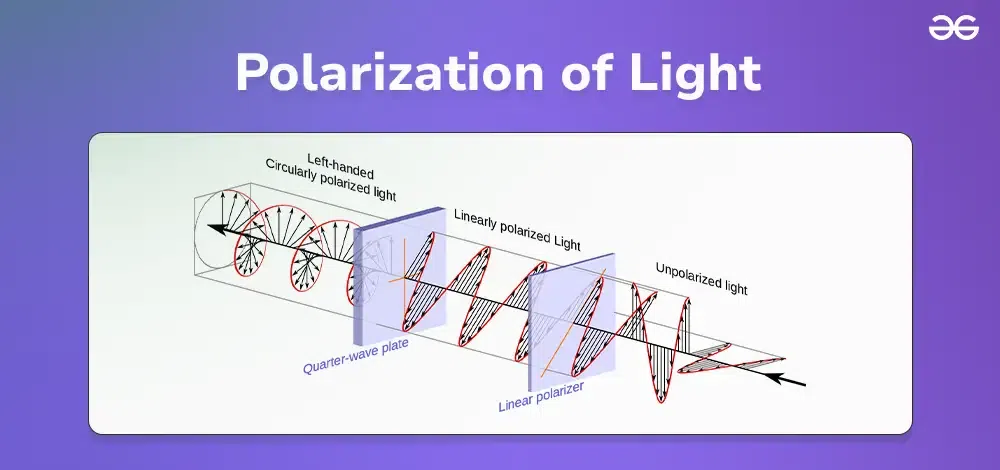
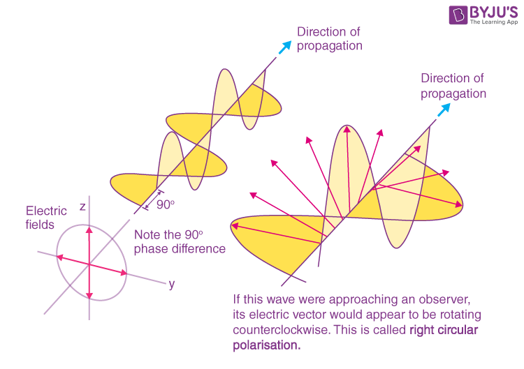
Circular Polarization
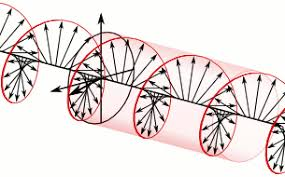
Circular polarization occurs when the electric field vector of light rotates in a circle as the wave propagates. Unlike linearly polarized light where the electric field oscillates in one fixed plane, in circularly polarized light, the tip of the electric field vector traces out a circular helix along the direction of propagation.
How It's Produced
Circularly polarized light consists of two perpendicular linearly polarized waves that have:
- Equal amplitude
- A phase difference of exactly 90° (π/2 radians) between them
When these two components combine, the resultant electric field vector rotates, creating circular polarization.
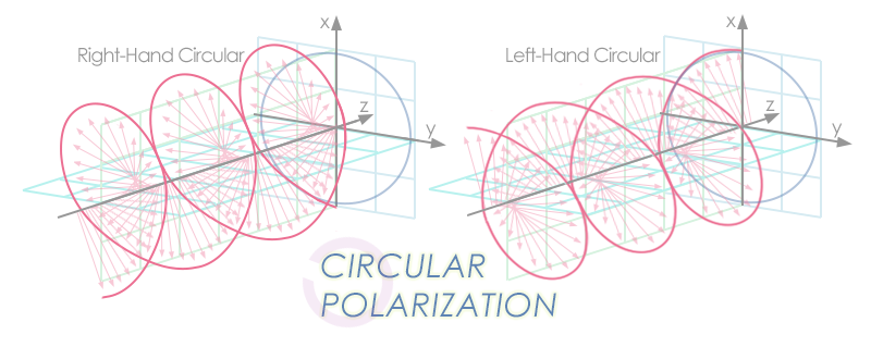
Two Types of Circular Polarization
-
Right-handed (Clockwise) Circular Polarization: If you look at the approaching light and the electric field vector appears to rotate clockwise, it's right-circularly polarized.
-
Left-handed (Counterclockwise) Circular Polarization: If the electric field vector rotates counterclockwise, it's left-circularly polarized.
Practical Production
The most common way to produce circularly polarized light is by passing linearly polarized light through a quarter-wave plate oriented at 45° to the polarization axis. The quarter-wave plate introduces a 90° phase difference between the two perpendicular components, creating circular polarization.
Applications
- 3D movies: Use circular polarization (left and right) for each eye
- Satellite communication: Circularly polarized antennas
- Optical experiments: Studying material properties and stress analysis
Elliptical Polarization
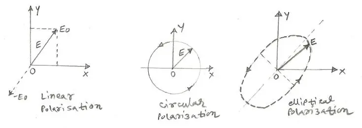
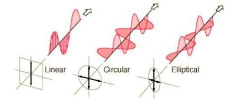
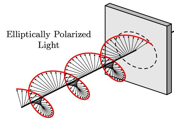
Elliptical polarization is the most general form of polarization. Here, the tip of the electric field vector traces out an ellipse as the wave propagates.
How It's Produced
Elliptical polarization results when you have two perpendicular linearly polarized waves with:
- Unequal amplitudes, OR
- A phase difference other than 90° (or both conditions)
The electric field vector both rotates AND changes its magnitude as the wave propagates.
Special Cases
- Linear polarization and circular polarization are actually special cases of elliptical polarization :
-
Linear: Phase difference = 0° (or 180°) → the ellipse collapses to a straight line
-
Circular: Phase difference = 90° AND equal amplitudes → the ellipse becomes a circle
-
Production
Elliptical polarization is produced by passing linearly polarized light through a quarter-wave plate at an angle other than 45° to the polarization axis.
Optical Activity
Optical activity (also called optical rotation) is the ability of certain substances to rotate the plane of polarization of linearly polarized light passing through them. When plane-polarized light enters an optically active material, the plane in which the electric field oscillates gradually rotates as the light travels through the substance.
Think of it like "rotating a screw" when we rotate a screw inwards through a material by using a screwdriver.
The "optically active" material in this case, would be whatever material the wall is made out of in which the screw is being driven into, and the angle of rotation will be given by the Specific rotation formula.
Key Characteristics
When linearly polarized light passes through an optically active substance:
- The light remains linearly polarized (it doesn't become circularly or elliptically polarized)
- However, the plane of polarization rotates by a certain angle
- The amount of rotation depends on the substance, its concentration (for solutions), and the path length the light travels through it.
The key insight: The light itself continues traveling straight forward, but the orientation of its electric field oscillation rotates around the direction of travel. This is exactly like a screw - the threads spiral around the shaft while the screw moves forward.
Two Types of Optically Active Substances
-
Dextrorotatory (d- or +): Rotates the plane of polarization to the right (clockwise) when viewed against the direction of light propagation.
- Example: D-glucose (dextrose)
-
Levorotatory (l- or -): Rotates the plane of polarization to the left (counterclockwise) when viewed against the direction of light propagation.
- Example: L-fructose
Why Does Optical Activity Occur?
Optical activity arises from the molecular structure of the substance—specifically from molecules that are chiral (they lack a plane of symmetry, like your left and right hands). These asymmetric molecules interact differently with left- and right-circularly polarized components of the light, causing the rotation.
Specific rotation formula
The angle of rotation (
where:
is the angle of rotation in degrees. is the specific rotation (a constant for each substance at a given wavelength and temperature). is the path length through the substance (typically in decimeters). is the concentration (for solutions, in ).
Applications
- Chemistry: Determining concentration and purity of sugar solutions (saccharimetry)
- Pharmaceuticals: Distinguishing between different forms (enantiomers) of drugs—some forms are active, others may be inactive or harmful.
- Food industry: Measuring sugar content in beverages.
- Quality control: Analyzing optical purity of chemical compounds
Common Optically Active Substances
- Sugars: Glucose, fructose, sucrose.
- Amino acids: Most naturally occurring amino acids
- Certain crystals: Quartz
- Biological molecules: Many proteins, DNA.
Measurement Device
The instrument used to measure optical activity is called a polarimeter. It works by:
- Passing plane-polarized light through the sample
- Measuring the angle by which the plane of polarization has rotated
- Using this angle to determine properties like concentration
Laser
LASER is an acronym for Light Amplification by Stimulated Emission of Radiation. It's a device that produces intense, highly directional, coherent, and monochromatic light through the process of stimulated emission.
Pre-requisites to understanding how LASER works.
Need to wind back to chemistry here for a bit.
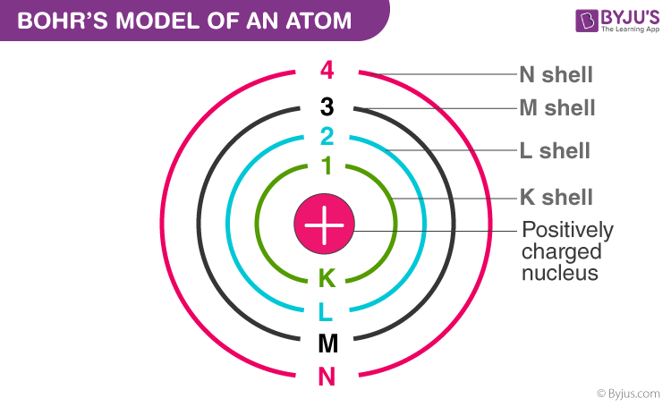
First of all, we need to know what Bohr's model of the atom is and how the shells are named.
And then come the states.
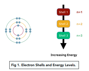
In an atom's ground state, electrons occupy their lowest possible energy levels, resulting in a stable atom with the shortest possible distance from the nucleus. When an atom absorbs energy, one or more electrons can jump to a higher energy level, entering an excited state. The atom then exists in this higher-energy, less stable state until the electron(s) fall back to a lower energy level, releasing the absorbed energy as light or heat.
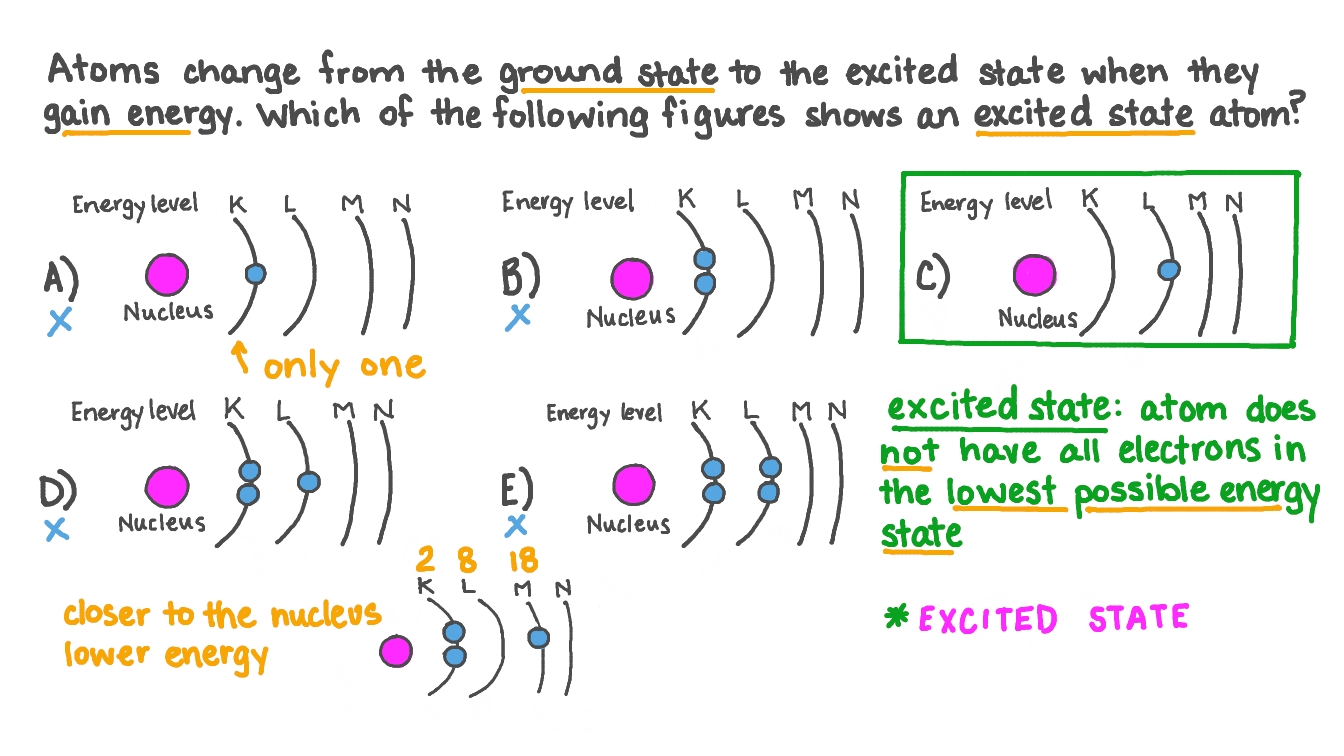
Ground State
Ground state is when an atom is in its lowest possible energy condition. Think of electrons like people in a building:
- Ground state: All the "people" (electrons) are on the lowest floors possible - ground floor, first floor, etc.
- This is the most stable, comfortable arrangement
- Electrons are closest to the nucleus (like being closest to the building's foundation).
- The atom is **content and doesn't want to change.
Excited State
Excited state is when the atom has more energy than its ground state. Continuing the building analogy:
- Excited state: Some "people" (electrons) have been pushed up to higher floors.
- This happened because energy was added from outside (like someone pushing them up the stairs)
- This is unstable - the "people" want to come back down to the lower floors.
- The atom is "restless" and will naturally **return to ground state.
Equilibrium -- Thermal Equilibrium vs Non-Equilibrium
What is Equilibrium in General?
Equilibrium means a balanced, stable state where nothing changes over time unless disturbed. Think of it like:
- A ball sitting at the bottom of a bowl (it stays there naturally).
- Water in a glass at room temperature (it doesn't heat up or cool down by itself).
- A seesaw that's perfectly balanced.
Thermal Equilibrium vs Non-Equilibrium
Thermal Equilibrium (Normal Condition)
Thermal equilibrium is the state where two or more systems or objects are at the same temperature and there is no net flow of heat between them. This condition is reached when heat energy has been evenly distributed throughout the systems, resulting in a stable and uniform temperature across all parts
In thermal equilibrium at normal temperatures :
- Most atoms prefer to be in ground state (like most people prefer to be on lower floors).
- Very few atoms are in excited states naturally.
- The system is balanced and stable.
- N₁ > N₂ (more atoms in ground state than excited state).
Non-Equilibrium Condition
"Non-equilibrium" describes a system that is not in thermodynamic equilibrium, a state where there is no net flow of matter or energy and the system is stable. Instead, a non-equilibrium state involves continuous transfer of energy and/or matter, leading to irreversible processes and a positive entropy production.
In non-equilibrium :
- We force the system out of balance by adding lots of energy.
- We can push more atoms into excited states than would naturally be there.
- This requires continuous energy input (like continuously pushing people up to higher floors).
- N₂ > N₁ (more atoms in excited state than ground state) - this is population inversion (we will study that in the sections below.)
Basic Principle of Laser Operation
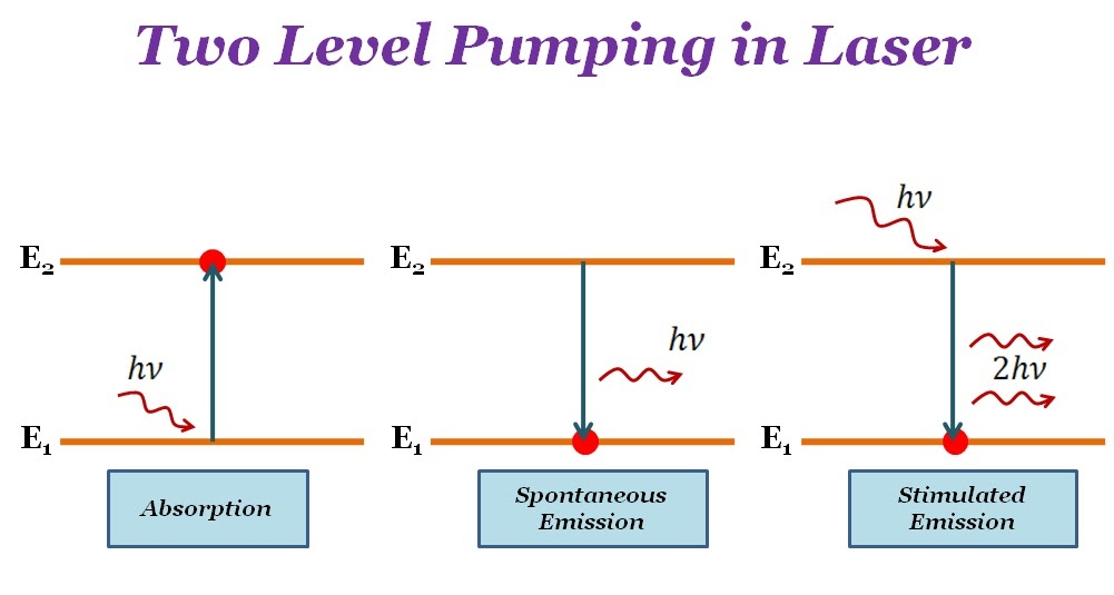
A laser works on the fundamental principle of stimulated emission. Here's the key process:
- Incident photon hits an excited atom.
- The atom releases another photon with identical properties (same frequency, phase, polarization, and direction)
- Now you have two identical photons where you started with one.
- These photons can hit more excited atoms, creating four photons, then eight, then sixteen...
- This creates a cascading amplification effect.
Population Inversion - The Heart of Laser Action
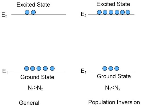
What is Population Inversion?
Population inversion is the non-equilibrium condition where more atoms are in the excited state than in the ground state.
Usually, more atoms are in the ground state than excited states. But for lasers to work, you need more atoms in an excited state than in the ground state — this reversed condition is called population inversion. It’s an unnatural state that requires continuous energy input (called pumping).
When one photon of the right energy hits an excited atom, it causes the atom to emit another identical photon in phase, doubling photons. These photons trigger more emissions from other excited atoms, causing an exponential chain reaction of photon multiplication.
Mathematically:
- N₂ = number of atoms in excited state
- N₁ = number of atoms in ground state
Why is Population Inversion Essential?
Under normal (thermal equilibrium) conditions:
- Most atoms prefer the ground state (lower energy).
- Incoming photons are absorbed rather than causing stimulated emission
- The laser chain reaction cannot occur.
With population inversion:
- More atoms are excited and ready to emit photons.
- Stimulated emission dominates over absorption.
- The laser amplification process can occur.
Pumping -- achieving population inversion
Pumping is the process of supplying energy to the laser medium to create and maintain population inversion.
Pumping is the term for supplying energy to the atoms in the laser medium to excite them from the ground state to higher energy (excited) states. The goal is to create a situation where more atoms are in an excited state than in the ground state—this is the population inversion required for laser action.
Why Do We Need Pumping?
- Under normal conditions (thermal equilibrium), almost all atoms prefer to stay in the ground state (lowest energy).
- Excited atoms naturally want to return to the ground state, releasing energy, usually as random light (spontaneous emission) or heat.
- To get more atoms in an excited state than in the ground state (population inversion), we must supply energy continuously and faster than the atoms can decay back down.
How Does Pumping Work?
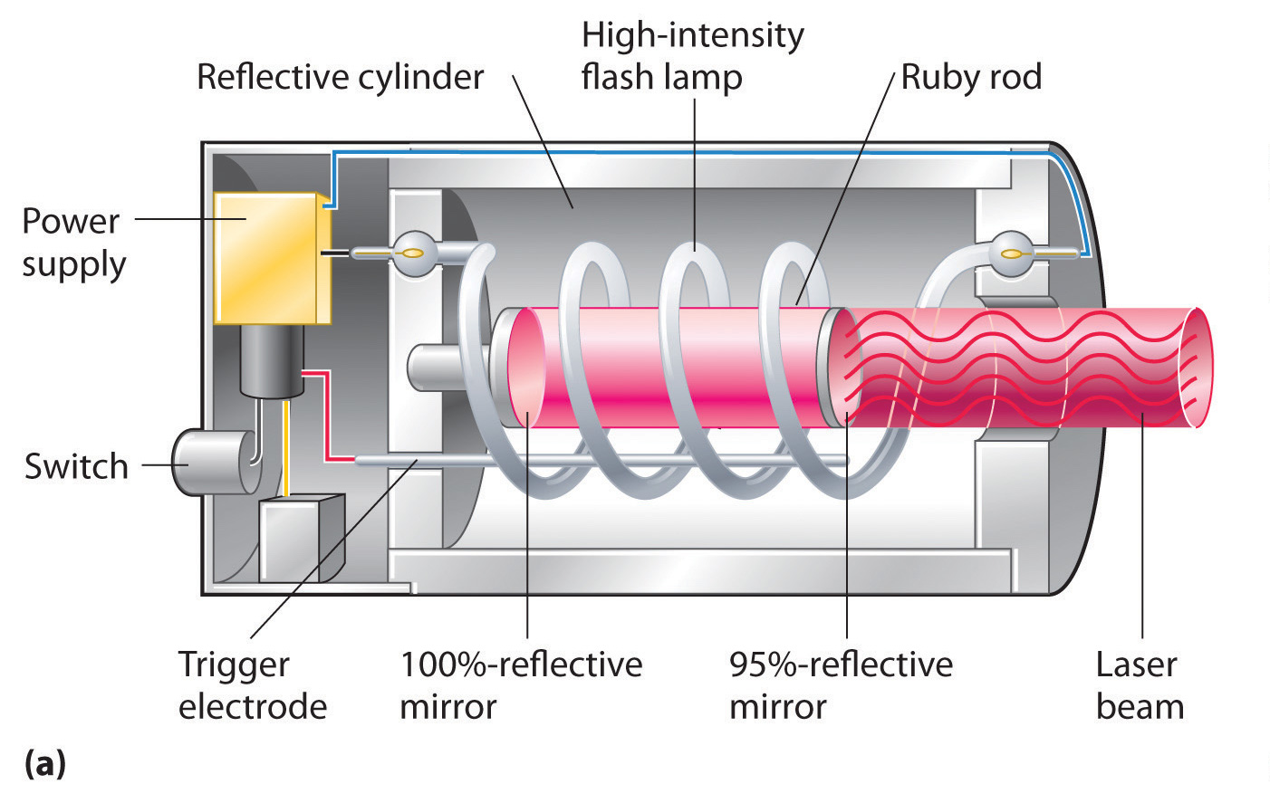
Common Pumping Methods:
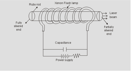
- Optical Pumping: Using intense light (e.g., flashlamp or another laser) to excite atoms—this is typical in solid-state lasers (like ruby lasers).
- Electrical Pumping: Using an electrical discharge to excite atoms—common in gas lasers (like helium–neon or argon lasers). Accelerated electrons collide with atoms, transferring energy.
- Thermal Pumping: In some cases, simply heating the medium can supply enough energy for population inversion.
- Chemical Pumping: Sometimes, chemical reactions produce excited molecules directly.
The Role of Threshold Pump Power
- Threshold pump power is the minimum rate at which energy must be supplied to achieve and maintain population inversion. If you pump energy too slowly, atoms just return to the ground state before enough can accumulate in the excited state for lasing to start.
- Once threshold is reached, stimulated emission can dominate—this is when laser action (amplified, coherent light) begins.
How it All Comes Together
- Think of pumping as "filling up" the higher floors of a building with people (atoms) faster than they can go back down.
- When there are more on the upper floors than the lower, a small trigger (like a photon) can set off a chain reaction where each excited atom releases a photon, making even more photons—this is laser light!
Types of pumping systems in laser
Two-level pumping in lasers.
How It Works
A two-level system has only:
- Ground state (
): Where atoms naturally reside. - Excited state (
): Where atoms are pumped.
The pump tries to excite atoms from
The Problem - Why It Doesn't Work
Population inversion is impossible in a two-level system.
Here's why:
-
When you pump atoms from
to , you simultaneously have stimulated absorption (pumping up) and stimulated emission (coming down). (Rapid de-excitation of the atoms.) -
At best, you can achieve equal populations (
), but you can **never get more atoms in than . -
The moment you approach equal populations, stimulated emission equals absorption, preventing further inversion.
Conclusion: Two-level lasers are theoretically impossible for practical laser action.
Three-Level pumping Laser System
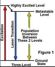
How It Works
A three-level system introduces a third energy level:
(Ground state): Starting point for all atoms. (Pump level): Short-lived excited state atoms are pumped to. (Metastable state): Long-lived intermediate state where atoms accumulate.
The Process:
- Atoms are pumped from
(optical/electrical pumping) - Atoms rapidly decay
(non-radiative, seconds) - Atoms accumulate in
(metastable, lifetime seconds) - Laser transition occurs:
(stimulated emission produces laser light)
Advantages
- Population inversion is achievable between E₁ and E₀
- Successfully demonstrated in real lasers
Limitations
- Requires very high pump power.
- Why? You must pump more than half the total atoms from the ground state to achieve .inversion, since the laser transition ends at the ground state.
- Typically operates in pulsed mode (short bursts).
- Not very efficient.
Example
Ruby Laser - the first working laser (1960)
Four-Level pumping laser system
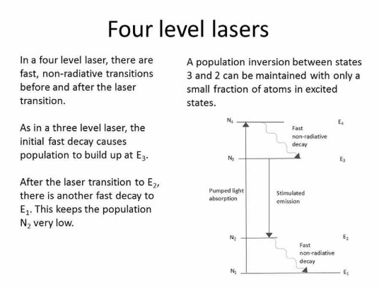
A four-level system adds a fourth level to improve efficiency:
- E₁ (Ground state): Starting point
- E₄ (Pump level): Short-lived state atoms are pumped to
- E₃ (Upper laser level): Metastable state where atoms accumulate
- E₂ (Lower laser level): Intermediate state above ground level
The Process:
- Atoms are pumped E₁ → E₄
- Rapid decay E₄ → E₃ (non-radiative, very fast)
- Atoms accumulate in E₃ (metastable, long lifetime)
- Laser transition: E₃ → E₂ (this produces the laser light)
- Rapid decay E₂ → E₁ (very fast, empties E₂ immediately)
Key Difference
The laser transition doesn't end at the ground state—it ends at
Advantages
- Much easier to achieve population inversion.
- Lower pump power required compared to three-level systems.
- Why? E₂ is nearly empty (rapidly decays to
), so you don't need to deplete the ground state—you just need > . - Can operate continuously (continuous wave mode).
- More efficient than three-level lasers.
- Population inversion possible even at low pump rates.
Requirements for Good Performance
-
(fast decay from pump level to upper laser level) -
(lower laser level empties much faster than upper laser level decays) -
must be sufficiently above E₁ so it's normally empty
Example
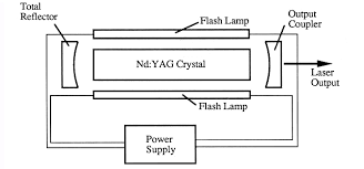
Nd:YAG Laser (Neodymium-doped Yttrium Aluminum Garnet) - widely used in industry, medicine, and military applications
Summary Comparison Table
| Feature | Two-Level | Three-Level | Four-Level |
|---|---|---|---|
| Population Inversion | Impossible | Possible but difficult | Easy to achieve |
| Pump Power Required | N/A | Very high (>50% of atoms) | Low |
| Efficiency | N/A | Low | High |
| Operation Mode | N/A | Pulsed | Continuous or pulsed |
| Laser Transition | N/A | Metastable → Ground | Upper laser → Lower laser (not ground) |
| Practical Use | No | Yes (Ruby laser) | Yes (Nd:YAG, He-Ne) |
| Threshold | N/A | High | Low |
Why Four-Level is Superior
The genius of the four-level system is that the lower laser level (E₂) is kept nearly empty by rapid decay to ground. This means:
-
You don't fight against a huge ground-state population
-
Even small pumping creates inversion between E₃ and E₂
-
Much more practical and efficient for continuous operation
Threshold Population Inversion
Threshold population inversion is the minimum level of population inversion (more atoms in an excited state than in the ground state) required for the laser to "turn on" and produce a stable, continuous beam of light. In simpler terms, it's the point where stimulated emission (the chain reaction that makes laser light) becomes strong enough to balance and then overpower all the losses in the system—like energy lost from imperfect mirrors, scattering, or absorption inside the laser medium
Why is There a Threshold?
- Inside a laser cavity, photons keep bouncing back and forth between mirrors.
- Every round trip, they amplify (get more photons from excited atoms) but also lose some energy to imperfect mirrors and scattering.
- For lasing to begin, the gain from stimulated emission must just balance out all these losses.
- The threshold is the condition when this balance is first achieved.
What Happens Below and Above Threshold?
-
Below threshold: The laser medium amplifies light a little, but losses dominate. Any light produced is weak, broad, and mostly random—no real laser beam.
-
At threshold: Gain from population inversion exactly equals losses. Laser just starts to oscillate—a fragile, narrow beam can appear.
-
Above threshold: The gain exceeds losses. The laser emits a strong, stable, narrow, monochromatic, and coherent beam—the classic laser effect.
How is Threshold Achieved?
- You pump the medium to drive up the number of excited atoms.
- The threshold pump power is the minimum energy input needed to reach threshold population inversion. You need to excite atoms faster than they return to the ground state.
- With enough energy supplied, the chain reaction of stimulated emission dominates, and the true laser light is produced.