Module 3 -- Electromagnetism and Dielectric Magnetic properties of materials
Index
- Maxwell's Laws and Equations -- Pre-requisites
- Gauss's Law (Maxwell's first equation)
- Gauss's law of magnetism (Maxwell's second equation)
- Maxwell's Third Equation -- Faraday's Law of Electromagnetic Induction
- Maxwell's fourth equation -- The Maxwell-Ampere Law
- Polarization, permeability and dielectric constant.
- Polar and Non-Polar Dielectrics
- Internal Fields in solids
- The Lorentz Method
- Clausius-Mossotti Equation
- Magnetization
- Susceptibility and Permeability in magnetic materials
- Relative Permeability
- Classification of Magnetic Materials
- 1. Diamagnetic Materials
- 2. Paramagnetic materials
- 3. Ferromagnetic Materials
- Ferromagnetism, Magnetic Domains and Hysteresis
- Magnetic Domains
- Hysteresis Loop
- Applications of Dielectrics
- Applications of Ferromagnetic materials
Maxwell's Laws and Equations -- Pre-requisites
Before we continue, I am assuming that like myself, you have been out of touch with physics for a really long time, so let's build this from the ground up, brick-by-brick.
Electric Fields and Forces
Electric charge is a fundamental property of matter that comes in two types: positive and negative. Like charges repel, unlike charges attract.
The electric field
where
Coulomb's Law
Coulomb's Law describes the magnitude of the electrostatic force between two stationary point charges, stating it is directly proportional to the product of the charges and inversely proportional to the square of the distance between them.
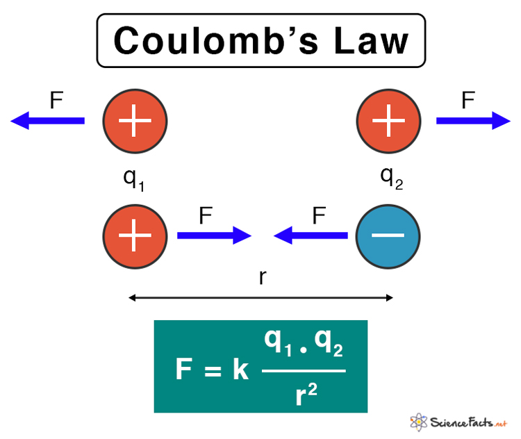
Key Principles of Coulomb's Law
- Direct Proportionality to Charge: The force is stronger if the charges are larger.
- Inverse Square Proportionality to Distance: The force decreases rapidly as the distance between charges increases.
- Attractive/Repulsive Force: The force is attractive if the charges are opposite in sign (one positive, one negative) and repulsive if they are the same (both positive or both negative).
The formula is given by:
or :
where:
is the Coulomb's constant. and are the magnitudes of the two point charges. is the distance separating the two charges. is the magnitude of the electrostatic force. : is the permittivity of free space, the capability of vacuum to permit electric field lines to pass through it. Higher permittivity means the medium can "accommodate" more electric field for the same conditions. (As explained in later sections).
What exactly is the permittivity of free space?
Some sources describe it as measuring the opposition offered against the formation of an electric field. Materials with higher permittivity offer more opposition to establishing an electric field.
These sound a bit contradictory, but really, they are not.
Higher permittivity means:
- The material opposes the electric field created by charges (reducing the field strength between them).
- BUT it also means the material can store more electric field energy and has greater polarization.
- This is because the material's polarization creates an internal field opposing the external field.
If all this didn't make sense, double back here once you are done reading and understanding till Internal Fields in solids.
Electric Flux
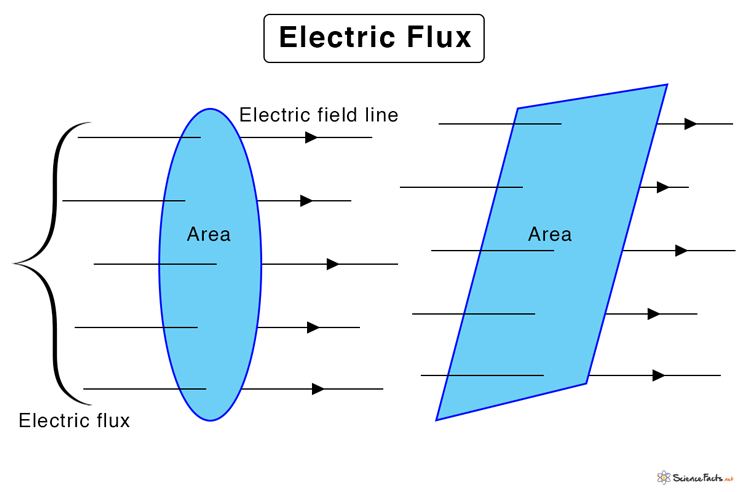
What exactly is flux?
In physics, flux refers to the measure of the rate at which a substance or field crosses a given surface. It quantifies how much of a vector quantity, such as an electric field, magnetic field, or fluid velocity, penetrates or passes through an area. The value of flux depends on the strength of the field, the area of the surface, and the orientation between the field and the surface.
Electric flux
This measures the amount of electric field lines passing through a given area. It's crucial for understanding concepts like Gauss's Law, which relates the total electric flux through a closed surface to the enclosed charge.
Gauss's Law (Maxwell's first equation)
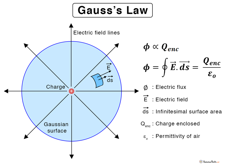
Gauss's Law for electricity, also known as the Gauss theorem, states that the total electric flux (the net count of electric field lines) through any closed surface (called a Gaussian surface) is directly proportional to the net electric charge enclosed within that surface, divided by the permittivity of free space (
The formula is:
where:
represents the total electric flux through the closed surface. is the total electric charge enclosed within the surface. is the permittivity of free space, a fundamental constant.
In differential form, this equation becomes:
where:
is the divergence operator. is the charge density. is the permittivity of free space, a fundamental constant.
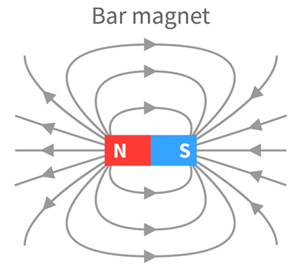
Magnetic Fields
A magnetic field is a region around a magnet or electric current where magnetic forces are present, acting on moving charged particles and magnetic materials. These fields originate from moving electric charges, such as electrons in atoms, and are described by magnetic flux density, with the unit Tesla. Magnetic fields are invisible but can be visualized with iron filings or compasses, and they are responsible for phenomena like attraction and repulsion between magnets and electric motors.
The force
Gauss's law of magnetism (Maxwell's second equation)
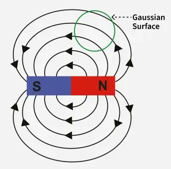
Gauss's second law of magnetism, or Gauss's law for magnetism, states that the net magnetic flux through any closed surface (or any gaussian surface) is zero, which is expressed mathematically as:
where:
represents the magnetic field. represents an infinitesimal area vector on the closed surface.
In differential form, this equation becomes:
where:
is the divergence operator.
This law implies that magnetic field lines form closed loops, as they do not start or end at isolated magnetic charges (magnetic monopoles), which do not exist according to current scientific understanding.
Explanation
- Magnetic Flux: Magnetic flux is the measure of the total number of magnetic field lines passing through a given area.
- Closed Surface: A closed surface is a surface that completely encloses a region of space, like a sphere or a cube.
- Zero Flux: The law states that if you draw any closed surface, the total magnetic flux entering the surface is equal to the total magnetic flux leaving it.
- No Magnetic Monopoles: Because the net flux is always zero, there can be no point sources of the magnetic field, meaning no magnetic monopoles (isolated north or south poles) exist.
Electric Potential and Voltage
We already covered potential energy and it's connection to force in Module 1 -- Mechanics -- Physics#Potential Energy function. where we learnt that in any system that physical systems always try to move from a higher potential energy to a lower potential energy, which can be visualized by the equation:
or better:
which shows the steepest descent (gradient descent) of the potential energy in the system.
In electric fields, the electric potential
The relationship between the electric field and it's potential is given by the same equation in a different form:
The work done in moving a charge in an electric field is given by :
where :
is the work done in moving the charge. is the electric charge(in coulombs) is the potential difference (voltage).
Hence why in situations with low voltage, we see lights with lesser intensity, fans moving slowly, since the electric charge moves very slowly, since the work done in moving the charge is very less.
Conversely, in high voltage situations, work done in moving the charges is too high, leading to a lot of electric charges moving in that system, and if one comes in contact with such a situation, it may prove fatal.
Maxwell's Third Equation -- Faraday's Law of Electromagnetic Induction
Now we come to one of the most revolutionary equations in physics - Faraday's Law of Electromagnetic Induction. This equation reveals something extraordinary: changing magnetic fields create electric fields.
Faraday's Law of Electromagnetic Induction states that a changing magnetic field creates an electromotive force (EMF) or voltage in a conductor, which can drive an electric current. The magnitude of this induced EMF is directly proportional to the rate at which the magnetic flux (the amount of magnetic field passing through a loop) changes over time.
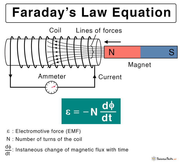
The equation given in the picture is a variation of the Maxwell's third equation, it's specifically for a magnet being moved through a copper coil.
However, Maxwell's third equation in it's proper integral form is:
In differential form it becomes:
Here's what this means: if you have a closed loop (like a wire), and the magnetic flux
Physical Meaning of Faraday's Law
In Module 1 -- Mechanics -- Physics#Conservative vs Non Conservative Forces we learnt that
A conservative force does the same amount of work regardless of the path taken between two points, such as gravity. In contrast, a non-conservative force's work depends on the path followed, and it often dissipates mechanical energy into forms like heat or sound, with examples including friction and air resistance.
Static electric fields are conservative - moving a charge around a closed loop does zero net work.
But Faraday's law changes everything: when magnetic fields vary with time, the induced electric field is non-conservative. You can extract energy by moving charges around a closed loop - this is how electric generators work!
Maxwell's fourth equation -- The Maxwell-Ampere Law
This is the final piece that completes Maxwell's equations. Just as Faraday showed that changing magnetic fields create electric fields, the Ampere-Maxwell law reveals the reverse relationship.
The equation is given by: (in it's integral form)
where:
is the permeability of free space. is the current enclosed by the loop. is the displacement current.
In differential form:
where:
is the current density.
Understanding the Two Terms
First term (Ampere's Original Law): Steady electric currents create magnetic fields that circulate around them. This is why a current-carrying wire creates a circular magnetic field pattern - the curl of
Second term (Maxwell's Addition - Displacement Current): This was Maxwell's revolutionary contribution. Even without physical current flow, a changing electric field creates a magnetic field. The quantity
Why Maxwell's Addition Was Necessary
Consider a charging capacitor (A capacitor is an electronic component that stores electrical energy in an electric field, acting like a temporary energy storage tank) with a current flowing in the wires. Between the capacitor plates, there's no physical current (it's a gap), but the electric field between the plates is increasing. Without Maxwell's displacement current term, Ampere's law would give different answers depending on which surface you chose for calculating enclosed current - a mathematical inconsistency!
Maxwell realized that the changing electric field between the plates acts like a current and produces the same magnetic field effect. This insight unified the equations and predicted electromagnetic waves!
The Beautiful Symmetry
Now notice the symmetry in Maxwell's equations:
- Faraday: Changing
(magnetic fields) creates (electric fields) . - Ampere-Maxwell: Changing
(electric fields) creates (magnetic fields).
This reciprocal relationship is what allows electromagnetic waves (light!) to propagate through space. A changing electric field creates a changing magnetic field, which creates a changing electric field, and so on - the wave sustains itself!
Summary of all four equations from Maxwell
- Gauss's Law (Maxwell's first equation):
- Gauss's law of magnetism (Maxwell's second equation):
- Maxwell's Third Equation -- Faraday's Law of Electromagnetic Induction:
- Maxwell's fourth equation -- The Maxwell-Ampere Law (The reverse of the third law):
These four equations completely describe all of classical electromagnetism! Everything from radio waves to X-rays, from motors to generators, from lightning to the behavior of atoms follows from these equations.
Polarization, permeability and dielectric constant.
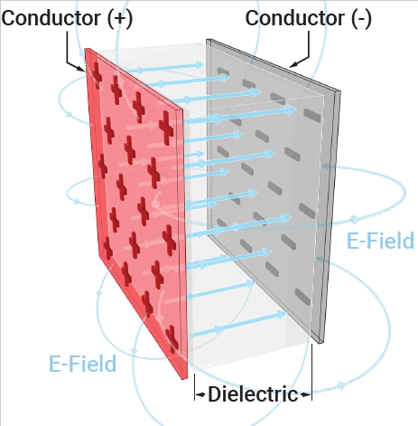
What are Dielectrics?
Dielectrics are electrical insulators that become polarized when an external electric field is applied, meaning their internal charges shift to form electric dipoles. This process, called dielectric polarization, creates an internal electric field that opposes the external field, effectively reducing the overall electric field inside the material. This is crucial for applications like energy storage in capacitors.
Dielectric materials can maintain an electrostatic charge while losing very little energy as heat. Mica, plastics, glass, porcelain, and other metal oxides are examples of dielectrics. It's also important to note that even dry air is dielectric
- An electrical insulator that does not have free-flowing electrons.
- Can be polarized by an external electric field.
- Examples include glass, plastic, mica, dry air, and distilled water.
What are Dipoles and what is an electric dipole?

A dipole is a pair of equal and opposite charges or magnetic poles separated by a distance. An electric dipole is a system of two equal and opposite electric charges separated by a small distance, which creates a net electric field. Molecules can have a permanent electric dipole if they have a separation of charge due to differences in electronegativity, like in a water molecule.
What is a dipole moment, and what is electronegativity?
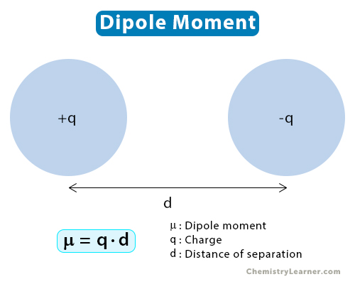
A dipole moment measures the separation of positive and negative charges in a molecule, arising from electronegativity differences between bonded atoms that create partial charges.
Electronegativity is the measure of an atom's tendency to attract a shared pair of electrons in a chemical bond. In molecules, different atoms have different electronegativities—the ability to attract electrons. When two atoms with different electronegativities form a bond, the shared electrons spend more time near the more electronegative atom. This creates a partial negative charge (
For example, in water (
Polarization (of dielectrics)
-
The process: When a dielectric is placed in an electric field, positive charges are slightly displaced in the direction of the field, and negative charges are displaced in the opposite direction. (Just like in polarization of light, where incident non-polar light is partially linearly polarized when it is reflected off of a surface around Brewster's angle)
-
Molecular effect: Molecules can gain a dipole moment, or existing permanent dipoles in polar materials can reorient to align with the field.
-
Internal field: The charge separation creates an internal electric field that opposes the external field.
-
Result: The net electric field inside the dielectric is reduced.
-
Polarization density: The dipole moment per unit volume is known as polarization density.
Why Polarization Matters
When a dielectric is placed between the plates of a capacitor:
-
The external electric field tries to shift positive charges one way and negative charges the other within each molecule.
-
This doesn’t create a flow of charge, but it does create "bound charges" that partially cancel out the original field inside the material.
This reduced field means a better capacitor: you store more charge for the same voltage!
Dielectric constant
The dielectric constant
- Vacuum: (
) - Water: (
) - Glass: (
)
When you place a dielectric material inside a capacitor it's capacitance changes from
Polar and Non-Polar Dielectrics
So, we already know what dipoles are and what a dipole moment is.
However,
Molecular Symmetry Matters
Here's the crucial point: just having polar bonds doesn't guarantee a polar molecule. The overall molecular geometry determines whether the individual bond dipoles cancel out or add up.
Non-Polar Dielectrics
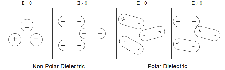
In this image the
Non-polar dielectrics are materials whose molecules have no permanent dipole moment. This happens when:
- The molecules are symmetric in shape.
- The charge distribution is uniform (no separation of positive and negative charge centers).
- Any polar bonds present are arranged symmetrically so their dipole moments cancel out.
Examples of Non-Polar Dielectrics
- Benzene (
): Perfectly symmetrical hexagonal ring structure. - Methane (
): Tetrahedral symmetry with identical bonds. - Nitrogen gas (
): Homonuclear diatomic molecule. - Carbon dioxide (
): Linear molecule with symmetric polar bonds. - Most noble gases (He, Ne, Ar): Monatomic, perfectly spherical.
Behavior in an Electric Field
When a non-polar dielectric is placed in an external electric field:
- The electron cloud around each atom/molecule gets distorted or displaced slightly from the nucleus.
- This creates induced dipoles - temporary dipoles that exist only as long as the field is applied.
- The induced dipole moment is proportional to the applied field:
, where is the polarizability. - When the field is removed, the molecules return to their symmetric, non-polar state.
This mechanism is called electronic polarization or induced polarization. The polarization is weaker compared to polar dielectrics.
Temperature Independence
Crucially, the polarization of non-polar dielectrics is independent of temperature. Since there are no permanent dipoles to be randomized by thermal motion, temperature changes don't significantly affect the electronic polarization mechanism
Polar Dielectrics
As you can see from this picture again, in the absence of electric fields, the dielectrics have a permanent dipole, since the positive and negative charges are separated out away from the nucleus. Also they are asymmetric, since the order of the distribution of charges in the dielectric is not fixed and appears random.
In the presence of an electric field however, all the dipoles in all the dielectrics seem to follow a symmetric order.
Now that's just a reverse of Non-Polar Dielectrics.
Polar dielectrics are materials whose molecules possess a permanent dipole moment even in the absence of an external electric field. This occurs when:
- ==The molecules have asymmetric shapes==.
- ==The centers of positive and negative charges do not coincide==.
- Polar bonds are arranged such that their dipole moments do not cancel out.
Examples of Polar Dielectrics
- Water (
): Bent shape with oxygen more electronegative than hydrogen, creating a net dipole. - Ammonia (
): Pyramidal shape with nitrogen at the apex. - Hydrogen chloride (
): Diatomic with much more electronegative than - Chloroform (
): Asymmetric tetrahedral structure. - Ethanol (
): Asymmetric with polar group.
Behavior WITHOUT an Electric Field
In the absence of an external field, the permanent dipoles in a polar dielectric are randomly oriented due to thermal agitation (random thermal motion). The dipoles point in all directions, so the net polarization is zero.
Behavior WITH an Electric Field
When an external electric field is applied:
- The permanent dipoles experience a torque that tries to rotate them to align with the field direction.
- This alignment is opposed by thermal motion, which tries to randomize the orientations.
- A partial alignment is achieved - not all dipoles align perfectly, but there's a net preference for field alignment.
- Additionally, the electron clouds still get distorted (electronic polarization), just like in non-polar materials.
So polar dielectrics exhibit both orientational polarization (rotation of permanent dipoles) and electronic polarization (induced dipoles).
The orientational polarization is typically much stronger than electronic polarization alone, making polar dielectrics have higher dielectric constants than non-polar ones.
Temperature Dependence - A Key Distinction
Here's a critical difference: the polarization of polar dielectrics is strongly temperature dependent.
Why? At higher temperatures, thermal agitation increases, making it harder for the electric field to align the dipoles. More molecules have enough thermal energy to overcome the aligning torque from the field.
As temperature increases:
- The dielectric constant decreases (at constant frequency)
- The degree of dipole alignment decreases
- Orientational polarization contribution decreases
At very high temperatures, thermal energy completely dominates, and even strong fields can barely align the dipoles.
Conversely, at lower temperatures, thermal motion is weaker, allowing better alignment and higher dielectric constants.
Summary Table: Polar vs Non-Polar Dielectrics
| Property | Non-Polar Dielectrics | Polar Dielectrics |
|---|---|---|
| Permanent dipole moment | Absent (zero) | Present |
| Molecular shape | Symmetric | Asymmetric |
| Charge distribution | Uniform, centers coincide | Non-uniform, centers separated |
| Polarization mechanism | Electronic (induced) only | Orientational + Electronic |
| Strength of polarization | Weaker | Stronger |
| Temperature dependence | Independent of temperature | Decreases with increasing temperature |
| Dielectric constant | Lower values | Higher values |
| Examples | Benzene, CH₄, N₂, CO₂ | H₂O, NH₃, HCl, alcohols |
The fundamental reason for all these differences traces back to whether the molecule has permanent dipoles that can rotate to align with the field (polar) versus only having temporary induced dipoles from electron cloud distortion (non-polar)
Internal Fields in solids
Why Do We Need to Consider Internal Fields?
Here's the key insight: when we place a dielectric in an external electric field
Problem
But what is this
No! The polarization of all the surrounding molecules creates additional electric fields that affect each molecule. So we need to find the actual field experienced by a molecule inside the dielectric.
The Lorentz Method
The brilliant physicist H.A. Lorentz developed a clever method to calculate the internal field. Here's how it works:
Step 1: Create an Imaginary Cavity
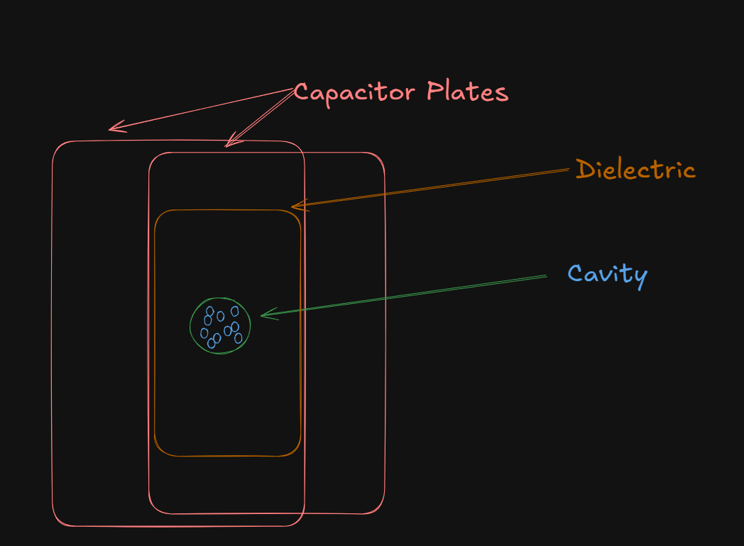
Imagine a dielectric material uniformly polarized by being placed between parallel capacitor plates. To find the internal field at a particular atom (let's call it atom C), we imagine carving out a small spherical cavity around that atom.
The cavity should be:
- Large enough on the atomic scale to contain many atoms (so we can treat the material outside as a continuum)
- Small enough on the macroscopic scale (so the field is essentially uniform across it)
Step 2: Break Down the Internal Field into Components
The total internal field
1. Component
This is the electric field that would exist between the capacitor plates if there were no dielectric (vacuum). It's simply the field due to the free charges on the capacitor plates.
If the electric flux density is
where:
2. Component
When the dielectric is polarized, bound charges (Bound charges are electric charges that are localized and held within atoms or molecules and cannot move freely, unlike free charges in conductors) appear on the surfaces of the dielectric (the surfaces facing the capacitor plates). These are the charges we discussed earlier - they create an internal field opposing the external field (when the dielectric is polarized i.e. subjected to an electric field).
This field opposed
where
3. Component
This is the electric field at the center of the spherical cavity due to all the polarized material outside the cavity. We treat this outer material as a uniformly polarized continuous medium(despite a small portion, the cavity, missing.)
The orange plate here is the uniformly polarized continuous medium, while the green sphere (the cavity) is the polarized sphere, due to it being covered with bound charges.
Now here's a beautiful result from electrostatics: when you have a uniformly polarized sphere, the field inside is uniform. When we remove material to create a spherical cavity in a uniformly polarized medium, the surface of the cavity becomes covered with bound charges.
Through integration over the spherical surface, this field is found to be:
This is called the Lorentz field or cavity field.
Component
This is the field at the center due to the discrete atoms or molecules inside the cavity (other than the central molecule we're considering).
In this diagram, the atoms inside the green cavity, are the small blue circles.
For cubic crystal structures and many symmetric arrangements, this field is zero due to symmetry. The dipoles inside the cavity are arranged symmetrically around the center, and their contributions cancel out.
For non-cubic structures,
So, for most purposes, we will just assume that
The Total Internal Field (Local Field).
Combining all our four components:
which gives us(yes I skipped the calculation):
where
This is the Lorentz local field formula! It's larger than the macroscopic field
Physical Interpretation
The local field is stronger than the average macroscopic field because:
- The cavity we created has polarization charges on its surface.
- These charges create an additional field (the Lorentz field
) that adds to the macroscopic field. - This extra field is what actually polarizes each individual molecule.
That's why the internal local field inside the dielectric opposes the external electric field, decreasing the net electric field in the capacitor, and allowing more charge to be stored for the same voltage.
Clausius-Mossotti Equation
The Clausius-Mossotti equation bridges the microscopic world (individual atoms and molecules) with the macroscopic world (bulk material properties). It connects the dielectric constant of a material to the polarizability of its individual molecules.
The Expression
The Clausius-Mossotti Equation is given by:
Understanding each variable
- This is a macroscopic property - it describes the bulk material's response to electric fields
- Dimensionless quantity (no units)
- Examples: Air ≈ 1, Water ≈ 80, Glass ≈ 4-10
- The number of molecules per unit volume
- Units:
(molecules per cubic meter) - Calculated as
, where is the mass density, is Avogadro's number, is the molar mass
- This is a microscopic property - it describes how easily an individual atom/molecule can be polarized.
- Units:
(Coulomb-meter squared per Volt) - Larger
means the molecule is more easily polarized - Related to dipole moment by
- A fundamental constant
- Same constant that appears in Coulomb's law
What the Equation tells us
The left side
The right side
The equation says: the bulk dielectric behavior of a material is the sum of the polarizability contributions from all its individual molecules, accounting for the local field effects.
Important Limitations
The Clausius-Mossotti equation has specific conditions where it works well:
-
Only for non-polar dielectrics or materials with **only induced polarization
-
Works for: N₂, CO₂, CH₄, H₂ gases
-
Does NOT work well for polar substances like water (which have permanent dipoles)
-
-
Assumes cubic symmetry or isotropic materials
- The
assumption we discussed earlier
- The
-
Valid at high frequencies for polar materials
- At high enough frequencies, permanent dipoles can't rotate fast enough to follow the field, so only electronic polarization matters
-
Low density and pressure for gases
- Works for N₂ up to 1000 atm between 25°C and 125°C
Magnetization
Just like we had electric dipoles (separated + and - charges) in dielectrics, we have magnetic dipoles in magnetic materials. But there's a crucial difference: magnetic monopoles don't exist. You can never isolate a single north pole or south pole - they always come in pairs.
Origin of Magnetic Dipoles in Atoms
1. Orbital motion of electrons
Electrons orbit around the nucleus, and this circular motion constitutes a current loop. Any current loop creates a magnetic field and has a magnetic dipole moment.
The magnetic dipole moment due to orbital motion is:
where
For an electron with charge
where
2. Spin of Electrons
Electrons also have an intrinsic property called spin - they act as if they're spinning on their own axis. This spin creates an additional magnetic dipole moment called the spin magnetic moment.
The electron magnetic moment due to spin is:
where:
3. Nuclear Spin (much weaker)
Nuclei can also have magnetic moments, but these are about 1000 times weaker than electron moments and usually negligible.
Net Magnetic Moment of an Atom
The total magnetic moment of an atom is the vector sum of all orbital and spin contributions from all its electrons:
In many atoms, these contributions cancel out completely, giving zero net magnetic moment. In others, they don't fully cancel, creating a permanent magnetic dipole.
Definition of Magnetization
Now we're ready for the formal definition! Magnetization (also called magnetic polarization) is defined as:
In words: Magnetization is the density of magnetic dipole moments in a material.
What the variables mean
- A vector quantity pointing in the direction of net magnetization
- SI Unit: Ampere per meter (A/m)
- Unit: Ampere-meter² (A·m²) or Joule per Tesla (J/T)
- Unit: cubic meters (m³)
The Analogy to Polarization
Notice the perfect analogy to dielectrics:
| Electric (Dielectrics) | Magnetic |
|---|---|
| Electric dipole moment |
Magnetic dipole moment |
| Polarization |
Magnetization |
| Measures density of electric dipoles | Measures density of magnetic dipoles |
| Unit: C/m² | Unit: A/m |
Just as polarization told us "how polarized" a dielectric is, magnetization tells us "how magnetized" a material is (how stronger the magnetic pull is of this material).
Behavior in Materials
Without an external magnetic field:
-
In most materials, atomic magnetic dipoles are randomly oriented due to thermal motion
-
The vector sum
, so -
The material shows no net magnetization
With an external magnetic field
-
The field tries to align the magnetic dipoles
-
Depending on the material type, dipoles may align with the field (paramagnetic), oppose it (diamagnetic), or strongly align (ferromagnetic)
-
The material develops a net magnetization
This is exactly analogous(similar) to how dielectrics develop polarization in an electric field.
Susceptibility and Permeability in magnetic materials
The Pre-requisites
1. Magnetic flux density(Magnetic Induction)
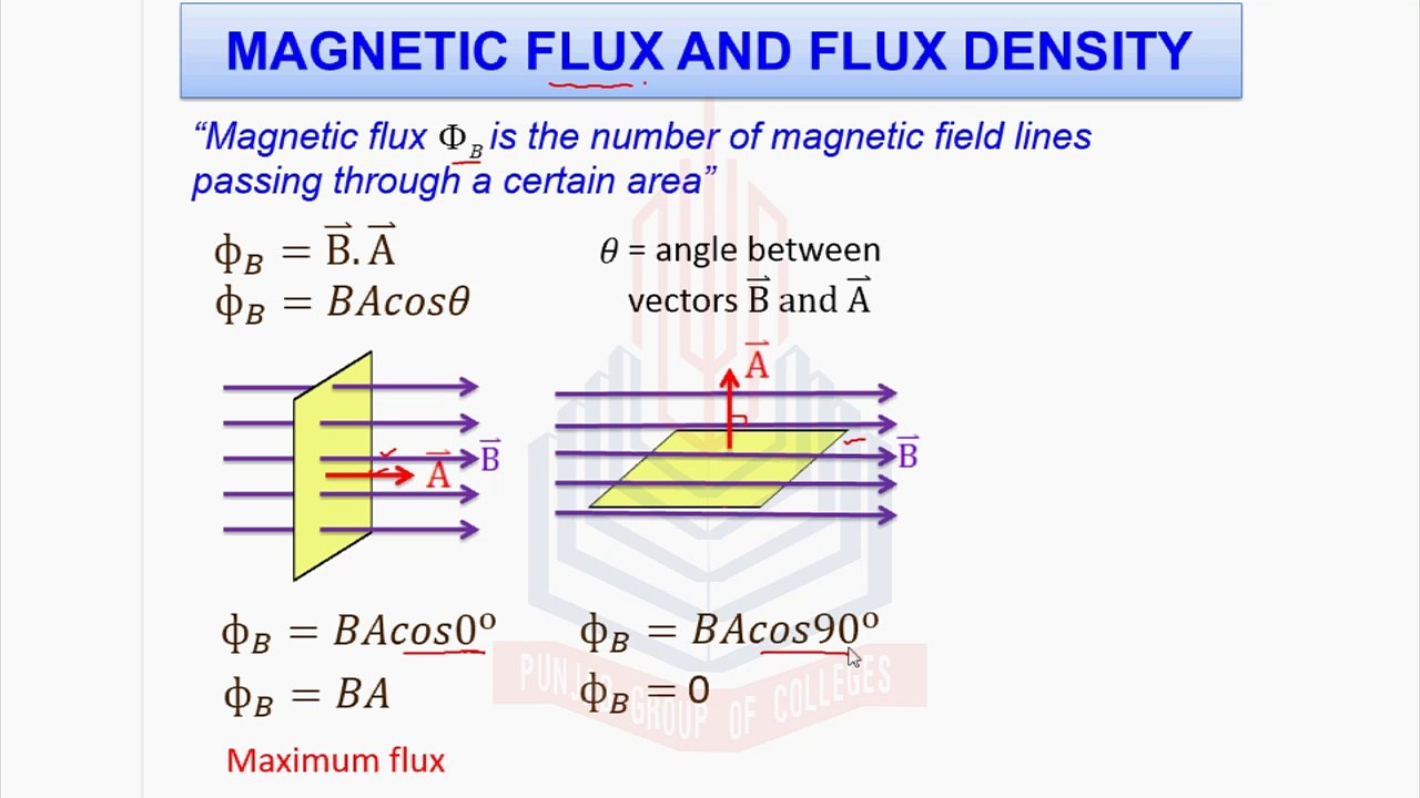
As we already know from What exactly is flux? flux is the rate at which a fluid or any substance passes through a given space or area.
In the case of Magnetic flux, as stated in the image, it is the number of magnetic field lines passing through a certain area.
So, the magnetic flux density is the magnetic flux per unit area.
It is given by the formula:
where:
is the magnetic flux density is the magnetic flux is the area.
2. Magnetic Field Intensity(Magnetizing field)
Magnetic field intensity (
This represents the applied magnetic field or the "driving force" for magnetization, excluding the contribution from the material's own magnetization.
It is given by the formula:
Relationship with Magnetic Flux Density(B) : Magnetic field intensity is related to magnetic flux density by the formula:
, where
Unit: Ampere per meter (A/m)
Relationship Between B, H, and M
The fundamental relationship connecting these quantities is
where:
, which is the permittivity of free space is the magnetization
Physical Meaning
The total magnetic field
- The external magnetizing field
- The magnetization of the material
Magnetic Susceptibility
https://www.youtube.com/watch?v=_9RcHLSmmjo
Magnetic susceptibility measures how easily a material can be magnetized in response to an applied magnetic field.
It's given by the formula:
or in vector form:
In words: Susceptibility is the ratio of induced magnetization (the external magnetic field) to the applied magnetic field intensity(how much external magnetic field needed to magnetize the material).
Key Properties
- Dimensionless quantity (no units)
- Can be positive or negative (unlike electric susceptibility, which is always positive)
: Material is paramagnetic (attracted to field) : Material is diamagnetic (repelled by field) : Material is ferromagnetic (strongly attracted)
Magnetic Permeability
Magnetic permeability describes a material's ability to support the formation of a magnetic field within itself(i.e. continue to stay a magnet and not revert back).
It is defined by the equation:
In words: Permeability is the ratio of magnetic flux density to magnetic field intensity.
SI Unit
- Henry per meter (H/m) or Newton per Ampere squared (N·A⁻²)
Physical Meaning
- Higher permeability → Material easily allows magnetic field lines to pass through → Better conductor of magnetic flux.
- Lower permeability → Material resists magnetic field lines.
This is the magnetic equivalent of permittivity
Relative Permeability
Just like we had relative permittivity (dielectric constant)
It is given by:
In words: Relative permeability is the ratio of the material's permeability to the permeability of free space.
- Dimensionless (no units)
- For vacuum:
- For diamagnetic materials
(slightly less than 1) - For paramagnetic materials
(slightly greater than 1) - For ferromagnetic materials
(can be thousands!)
Think of it this way:
- Higher permeability = Material is a better conductor of magnetic flux = Magnetic field lines pass through easily.
- Lower permeability = Material is a poorer conductor of magnetic flux = Harder for magnetic field lines to pass through.
Vacuum (air) is actually the POOREST conductor of magnetic flux. That's why
| Permittivity (Electric) | Permeability (Magnetic) |
|---|---|
| ==Describes how vacuum permits/supports electric fields== | ==Describes how vacuum permits/supports magnetic fields== |
| Opposes formation of electric fields (reduces field strength) | Permits formation of magnetic fields (conducts magnetic flux) |
| Higher |
Higher |
| Vacuum has minimum |
Vacuum has minimum |
| Dielectrics have |
Magnetic materials have |
Why the Language Differs
The terminology difference exists because:
For electricity: We often focus on how materials weaken the electric force between charges (Coulomb's law). Higher permittivity → more "opposition" → weaker force read What exactly is the permittivity of free space? again to understand why the opposition is better.
For magnetism: We focus on how materials conduct magnetic flux. Higher permeability → better "conduction" → stronger magnetic field.
Both are valid perspectives on the same underlying physics!
Classification of Magnetic Materials
Overview Table
| Property | Diamagnetic | Paramagnetic | Ferromagnetic |
|---|---|---|---|
| Susceptibility χmχm | Negative (small) | Positive (small) | Positive (very large) |
| Typical χmχm value | |||
| Relative permeability μrμr | < 1 (slightly | > 1 (slightly) | >> 1 (thousands) |
| Behavior in magnetic field | Weakly repelled | Weakly attracted | Strongly attracted |
| Temperature dependence | Independent | Inversely proportional | Complex |
Now let's understand each one brick-by-brick!
1. Diamagnetic Materials
Basic Characteristics
Diamagnetic materials are weakly repelled by magnetic fields. They create a small magnetic field opposite to the applied field.
Key properties:
- Negative susceptibility:
- Relative permeability:
(typically ) - Magnetization opposes the applied field:
is antiparallel to
The same principle works at the atomic level:
- When you apply an external magnetic field to an atom, the magnetic flux through the electron orbits changes.
- By Lenz's law, this changing flux induces currents in the electron orbits that oppose the applied field.
- These induced currents create tiny magnetic moments opposing the external field.
- Result: The material is weakly repelled.
This is why diamagnetism is universal — it occurs in all materials without exception, because all materials have electrons in orbits. However, it's often masked by stronger paramagnetic or ferromagnetic effects.
Temperature Independence
Diamagnetism is independent of temperature. The induced currents depend only on the applied field, not on thermal motion. This makes sense because it's a forced response (induced by the field), not a thermal alignment effect.
Examples of Diamagnetic Materials
- Bismuth (Bi) — strongest diamagnet among common elements
- Copper (Cu)
- Gold (Au)
- Silver (Ag)
- Water (H₂O)
- Most organic compounds
- Superconductors (perfect diamagnets with
)
2. Paramagnetic materials
Paramagnetic materials are weakly attracted by magnetic fields. They create a small magnetic field parallel to the applied field.
Key Properties
- Positive susceptibility:
(small) - Relative permeability:
(typically ) - Magnetization aligns with the applied field:
is parallel to - Magnetization disappears when the field is removed.
Mechanism: Permanent Dipoles with Thermal Randomization
Paramagnetic materials contain atoms with permanent magnetic dipole moments due to unpaired electrons.
The physics:
-
Without external field: The permanent magnetic dipoles are randomly oriented due to thermal agitation. Net magnetization
. -
With external field: The field exerts a torque on each dipole, trying to align it with the field direction. This is similar to how permanent electric dipoles in polar dielectrics align with electric fields.
-
Competition: Thermal energy tries to randomize the orientations, while the magnetic field tries to align them.
-
Result: Partial alignment is achieved — the material becomes weakly magnetized in the same direction as the field.
Curie's Law: Temperature Dependence
The susceptibility of paramagnetic materials follows Curie's Law:
where
Physical meaning: As temperature increases, thermal agitation becomes stronger, making it harder to align the dipoles. Therefore, magnetic susceptibility decreases with increasing temperature.
This is exactly analogous to polar dielectrics, where higher temperature reduces the ability to align permanent electric dipoles!
Examples of Paramagnetic Materials
- Aluminum (Al)
- Platinum (Pt)
- Manganese (Mn)
- Oxygen (O₂) gas
- Most transition metal salts
- Materials with unpaired electrons
3. Ferromagnetic Materials
Basic Characteristics
Ferromagnetic materials are strongly attracted by magnetic fields and can become permanent magnets. This is the most important and complex category!
Key Properties
- Very large susceptibility:
(hundreds to thousands) - Relative permeability:
(can be 10,000 to 100,000!) - Retain magnetization even after the external field is removed.
- Show hysteresis (more on this in the later sections) — magnetization depends on magnetic history.
- Exhibit magnetic domains.
What Makes Ferromagnetism Special?
The key difference from paramagnetism is the quantum mechanical exchange interaction between neighboring atoms. In ferromagnetic materials, there's a strong force that makes neighboring atomic magnetic dipoles want to align parallel to each other, even without an external field.
This creates regions called magnetic domains where millions of atomic dipoles are already perfectly aligned.
Temperature Dependence: Curie Temperature
Ferromagnetic materials remain ferromagnetic only below a critical temperature called the Curie temperature
Above
Curie temperatures of common ferromagnets:
-
Iron (Fe):
(770°C) -
Nickel (Ni):
(354°C) -
Cobalt (Co):
(1115°C)
Examples of Ferromagnetic Materials
- Iron (Fe) — most common ferromagnet
- Nickel (Ni)
- Cobalt (Co)
- Gadolinium (Gd)
- Alloys: Steel, permalloy, alnico
Summary: Why Materials Behave Differently
Diamagnetic: ALL materials have this effect (induced opposing field from Lenz's law), but it's weak.
Paramagnetic: Materials with unpaired electrons have permanent dipoles that can partially align with the field, but thermal motion fights this alignment.
Ferromagnetic: Materials with strong exchange interaction form domains of aligned dipoles, leading to dramatic magnetic enhancement. This only works below the Curie temperature.
The Beautiful Parallel
Here's the complete analogy table showing the parallels between dielectrics and magnets:
| Electric (Dielectrics) | Magnetic |
|---|---|
| Non-polar dielectrics | Diamagnetic materials |
| No permanent electric dipoles | No permanent magnetic dipoles |
| Induced polarization (electron cloud shifts) | Induced magnetization (orbital currents) |
| Internal field opposes external field | Magnetization opposes external field |
| Temperature independent | Temperature independent |
| Universal (all materials) | Universal (all materials) |
| Weaker effect | Weaker effect |
| Polar dielectrics | Paramagnetic materials |
| Permanent electric dipoles | Permanent magnetic dipoles (unpaired electrons) |
| Orientational polarization (dipole rotation) | Dipole alignment |
| Thermal randomization | Thermal randomization |
| Partial alignment with field | Partial alignment with field |
| Strong temperature dependence | Curie's Law: |
| Stronger effect than non-polar | Stronger than diamagnetic |
| Magnetization lost when field removed | Magnetization lost when field removed |
| No electric equivalent | Ferromagnetic materials |
| (No spontaneous polarization at room temp) | Spontaneous magnetization in domains |
| — | Exchange interaction aligns neighbors |
| — | Permanent magnets possible |
| — | Hysteresis effects |
The analogy breaks down at ferromagnetism because there's no electrical equivalent at room temperature! Ferroelectric materials exist but behave quite differently and typically only work at very low temperatures or special conditions.
Ferromagnetism, Magnetic Domains and Hysteresis
Ferromagnetic materials have a unique property: spontaneous magnetization. Even without any external magnetic field, the atomic magnetic moments in ferromagnets naturally want to align parallel to each other due to a quantum mechanical effect called the exchange interaction.
But here's the puzzle: if all the atomic moments want to align, why isn't every piece of iron a strong permanent magnet? The answer lies in magnetic domains.
Magnetic Domains
Definition
A magnetic domain is a small region within a ferromagnetic material where all the atomic magnetic moments are perfectly aligned in the same direction. Think of it as a tiny region that's already a perfect magnet internally.
Size: Domains are typically microscopic, ranging from a few micrometers to millimeters, depending on the material.
Why Do Domains Form?
If the exchange interaction makes all magnetic moments want to align, why doesn't the entire piece of iron become one giant domain with all moments pointing the same way?
The answer: Energy minimization
Single Domain State (High Energy)
Imagine a piece of iron where all magnetic moments point in the same direction throughout the entire material. This creates:
- A strong magnetic field extending far outside the material.
- This external magnetic field stores a lot of magnetostatic energy (energy stored in the magnetic field).
- Nature doesn't like high energy states.
Multiple Domain State (Lower Energy)
The material can lower its energy by splitting into multiple domains with magnetization pointing in different directions:
- ==Adjacent domains have magnetization in opposite or perpendicular directions==
- The magnetic field lines now form closed loops inside the material
- Much less magnetic field extends outside the material
- Less magnetostatic energy is stored
- Total energy is lower → more stable configuration
The trade-off: Creating domain boundaries (domain walls) costs some energy, but the reduction in magnetostatic energy more than compensates for it.
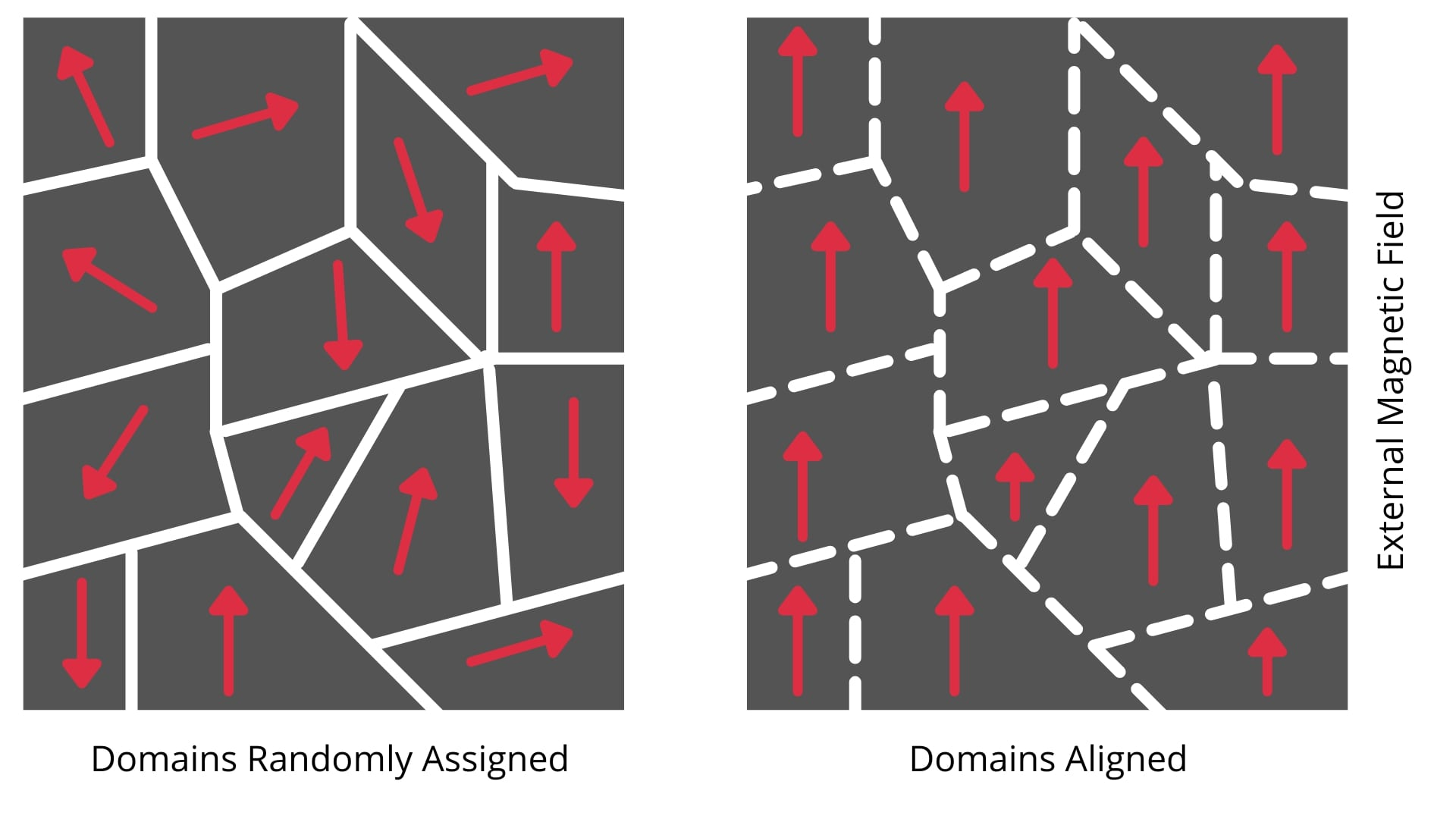
Structure of Unmagnetized Ferromagnet
In an unmagnetized piece of ferromagnetic material (like a fresh iron nail):
- The material contains many domains pointing in **random directions.
- Each individual domain is fully magnetized.
- But the net magnetization of the entire material is zero because the domain magnetizations cancel out.
- This is why an ordinary iron nail doesn't act like a magnet.
Domain Walls
What Are Domain Walls?
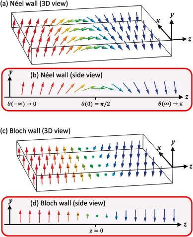
Domain walls (also called Bloch walls) are the boundaries between adjacent magnetic domains. They're regions where the magnetization gradually rotates from the direction in one domain to the direction in the neighboring domain.
Thickness: Typically 10-1000 atomic layers thick, depending on the material.
Structure: The magnetic moments don't flip abruptly at the boundary; instead, they rotate smoothly over many atomic layers. This gradual rotation minimizes the exchange energy cost.
Types of Domain Walls
- 180° domain wall: Magnetization rotates by 180° (opposite directions)
- 90° domain wall: Magnetization rotates by 90° (perpendicular directions)
Magnetization Process: How Domains Respond to External Fields
Now comes the exciting part! When you apply an external magnetic field to a ferromagnetic material, the domains respond in two main ways:
Process 1: Domain Wall Motion (Lower Fields)
At low to moderate field strengths:
- Domains whose magnetization is aligned with the external field are energetically favorable
- These favorable domains grow at the expense of unfavorable domains
- This happens through **domain wall movement
- The walls literally move through the material, shifting the boundaries
- Net result: The material develops increasing magnetization in the direction of the applied field
This is reversible at low fields — remove the field, and walls can move back.
Process 2: Domain Rotation (Higher Fields)
At higher field strengths:
- Most domains are now aligned with the field through wall motion
- Remaining domains not perfectly aligned begin to rotate their magnetization toward the field direction
- This requires more energy than domain wall motion
- Eventually, at saturation, all domains point in the field direction
- The material is now a single domain — fully magnetized
Hysteresis Loop
This is one of the most important concepts in ferromagnetism! Hysteresis means the magnetization lags behind the applied field and depends on the magnetic history of the material.
Physical Significance of Hysteresis
Why Hysteresis Occurs
Domain wall pinning: As domain walls move through the material, they encounter defects (impurities, dislocations, grain boundaries) that pin them in place. Energy is needed to unpin them, which is why the magnetization lags behind the field. This right here causes the magnetic material to retain the magnetization even after the field is removed, since these domains don't go back to their original positions as they get stuck.
Retentivity (Remanence)
Retentivity exists because of pinning:
- After saturating the magnet, favorable domains have grown large.
- When you remove the external field, domain walls want to move back to reduce magnetization
- But they're pinned at defects and can't move freely
- Result: The material retains significant magnetization even at
- This is why permanent magnets work!
Energy Loss
The area inside the hysteresis loop represents energy dissipated as heat during one complete magnetization cycle. This energy goes into moving domain walls against friction/pinning.
Summary: The Complete Picture
Unmagnetized ferromagnet:
- Many randomly oriented domains
- Net magnetization = zero
Apply external field:
- Domain walls move (favorable domains grow)
- Domain rotation at higher fields
- Saturation: single domain state
Remove field:
- Domains don't return to original state (pinning)
- Retentivity: Material stays magnetized
- This is how permanent magnets work
Hysteresis loop:
- Shows magnetization vs. field relationship
- Loop area = energy loss
- Shape determines applications
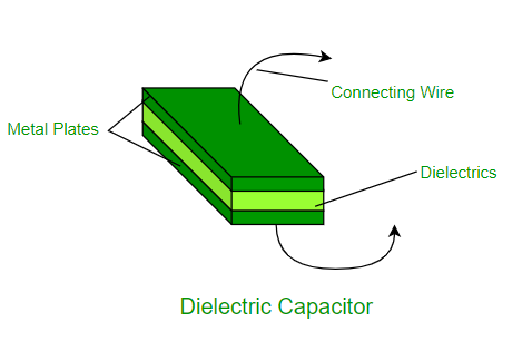
Applications of Dielectrics
Dielectric materials have numerous applications, primarily in energy storage (capacitors), electrical insulation, and high-frequency devices like microwave ovens. They are also used in electronics for components like semiconductors and memory devices, and in other areas such as medical imaging, LCD displays, and dielectric heaters.
Energy storage and transmission
-
Dielectrics form the insulating layer between capacitor plates, preventing them from touching and allowing energy to be stored.
-
They prevent electrical current from flowing between conductors in applications like cables and electronic circuits.
-
Liquid dielectrics, such as mineral oil, are used in transformers to provide insulation and aid in cooling.
Electronics and semiconductors
-
Semiconductor devices:
High-permittivity dielectrics are used to improve the performance of semiconductor devices.
-
Dielectrics are used as gate dielectrics in the manufacturing of transistors.
-
Certain dielectrics, like ferroelectrics and electrets, are used to store information.
High-frequency applications
-
The heating process in a microwave oven relies on the dielectric loss of water, which absorbs microwave energy and turns it into heat.
-
Radio Frequency (RF) devices:
Low-dielectric-loss materials are essential for high-frequency applications like RF devices to maintain efficiency.
-
Ceramic dielectrics are used in dielectric resonator oscillators (DROs) for frequency control in electronic circuits.
Other applications
-
Dielectric properties can be used for diagnostic purposes to visualize tissues.
-
Liquid Crystal Displays (LCDs):
Dielectrics are a key component in the functioning of LCDs.
-
These are dielectrics that have a permanent electric charge, acting as an electrostatic equivalent to magnets.
-
Dielectric heating:
This process uses dielectric materials to heat things like glues, foam rubber, and plastics through the use of an alternating electric field.
Applications of Ferromagnetic materials
-
Electric Motors and Generators:
Used to create powerful permanent magnets that are essential for the rotation of electric motors and the generation of electricity in generators.
-
Transformers and Inductors:
Soft iron and other ferromagnetic materials are used for cores because of their high magnetic permeability, which concentrates magnetic flux and improves efficiency.
-
Electromagnets:
Used to create temporary magnetic fields that can be turned on and off, which are crucial for devices like relays and actuators.
-
Loudspeakers and Telephones:
Permanent magnets in these devices use ferromagnetic materials to produce sound by moving a diaphragm in response to an electric signal.
Magnetic storage
-
Hard Drives:
The platters in a computer's hard drive are coated with a ferromagnetic material, which can be magnetized in tiny regions to store data.
-
Magnetic Tapes and Strips:
Ferromagnetic particles are used on magnetic tapes and credit card strips to record and store information.
Other applications
-
Compasses:
The needle of a compass is a small, magnetized piece of ferromagnetic material that aligns itself with the Earth's magnetic field.
-
Sensors and Actuators:
Ferromagnetic materials are used in a variety of sensors and actuators for position sensing and controlling mechanical movements.
-
Magnetic Alloys:
Materials like steel and permalloy, which are ferromagnetic, are used in many applications where their magnetic properties are beneficial.